LINXON Description | 4
LX218-Operating-Manual-en1-04-(1908) 25 / 90
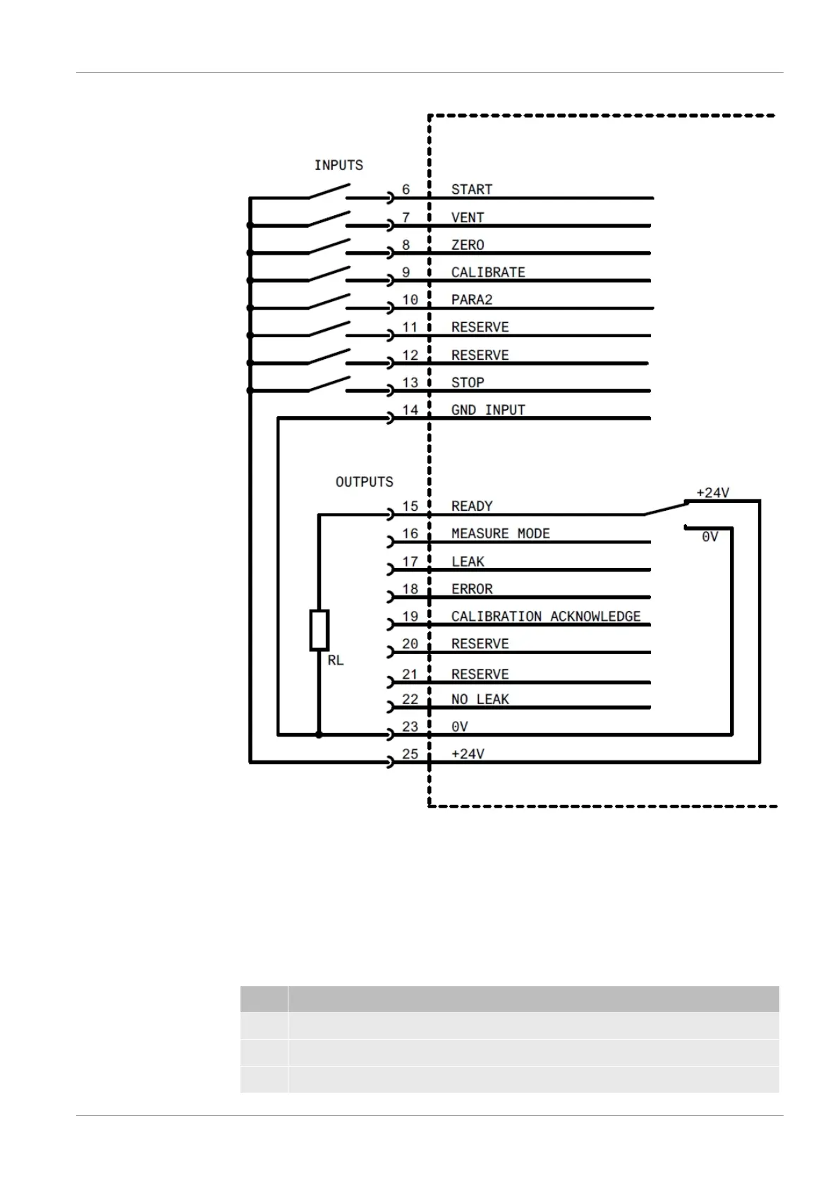
Examples of digital
inputs
Fig.9:
Examples of digital inputs
There must be a connection between Pin 14 and Pin 23 during actuation using the
+24 V of the leak detector.
Remote control unit
This remote control interface is designed as a serial interface to control the device via
the remote control unit when using the wired version. The remote control unit can be
connected via a connection cable with an RJ45 connector (Fig. 10-2/5). The remote
control unit is not part of the normal delivery for the device.
Pin Signal
2 +24 V (0.8 A slow-blowing fuse)
3 0 V DGND (0 V)
4 RxD (intern. RS232)