6
X1 - X1 ALU
Insert always an articulated joint between the chain and the anchor so that the chain itself does not turn into as spiral.
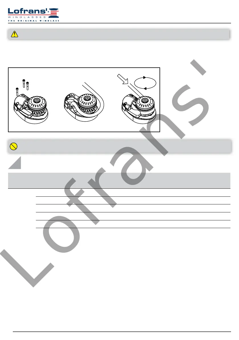
3.9 Chain insertion
In order to guarantee performances and reliability, it is recommended to use a calibrated chain of the measure corresponding to the
gipsy supplied.
4.1 Electrical cable section
In order to obtain the maximum performances from the anchor windlass and safeguard the electrical system, it is essential that the
anchor windlass be wired with cables of sufcient section as suggested in the table.
4.2 Solenoid valves (Control Box)
Place it in a dry place near the capstan.
4.3 Circuit breakers
The circuit breakers recommended by Lofrans’ have an intervention curve and not a simple plate value. The switches selected for each
model guarantee the correct operation of the system.
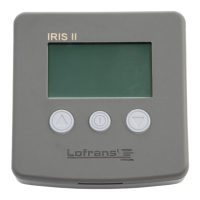
4.4 Remote control electric panel board
The remote control electric panel board must be mounted in a comfortable position (such as the deck, the rudder or the cockpit), so that
the operator can see the capstan during the manoeuvre. Mount and seal the electric panel board so that the terminals remain in a dry
place.
1. Remove the covering hood by
unscrewing the two seal screws.
2. Insert the chain into the hole and x
to a safe point.
3. Replace the hood by screwing the
xing screws.
4. Wrap the chain in the gipsy.
5. Recover all the chain by using the
motor, taking care that the chain
enters into the gipsy well aligned.
4 ELECTRICAL SYSTEM
Model
Motor Power
(W)
Voltage (V)
Contactor
(A)
Cable sizing according length of cable (positive + negative)
0-15 m 0-50 ft 15-25 m 50-75 ft
X1/X1 Alu
500 12 16 mm
2
6 AWG 25 mm
2
4 AWG
500 24 10 mm
2
8 AWG 10 mm
2
8 AWG
800 12 16 mm
2
6 AWG 25 mm
2
4 AWG
800 24 10 mm
2
8 AWG 10 mm
2
8 AWG
1000 12 25 mm
2
4 AWG 35 mm
2
0 AWG
1000 24 16 mm
2
6 AWG 25 mm
2
4 AWG
ATTENTION! Always disconnect electrical power to the anchor windlass before carrying out any operation.
1
2
3
UP