Operation control
Operation control 2-
7
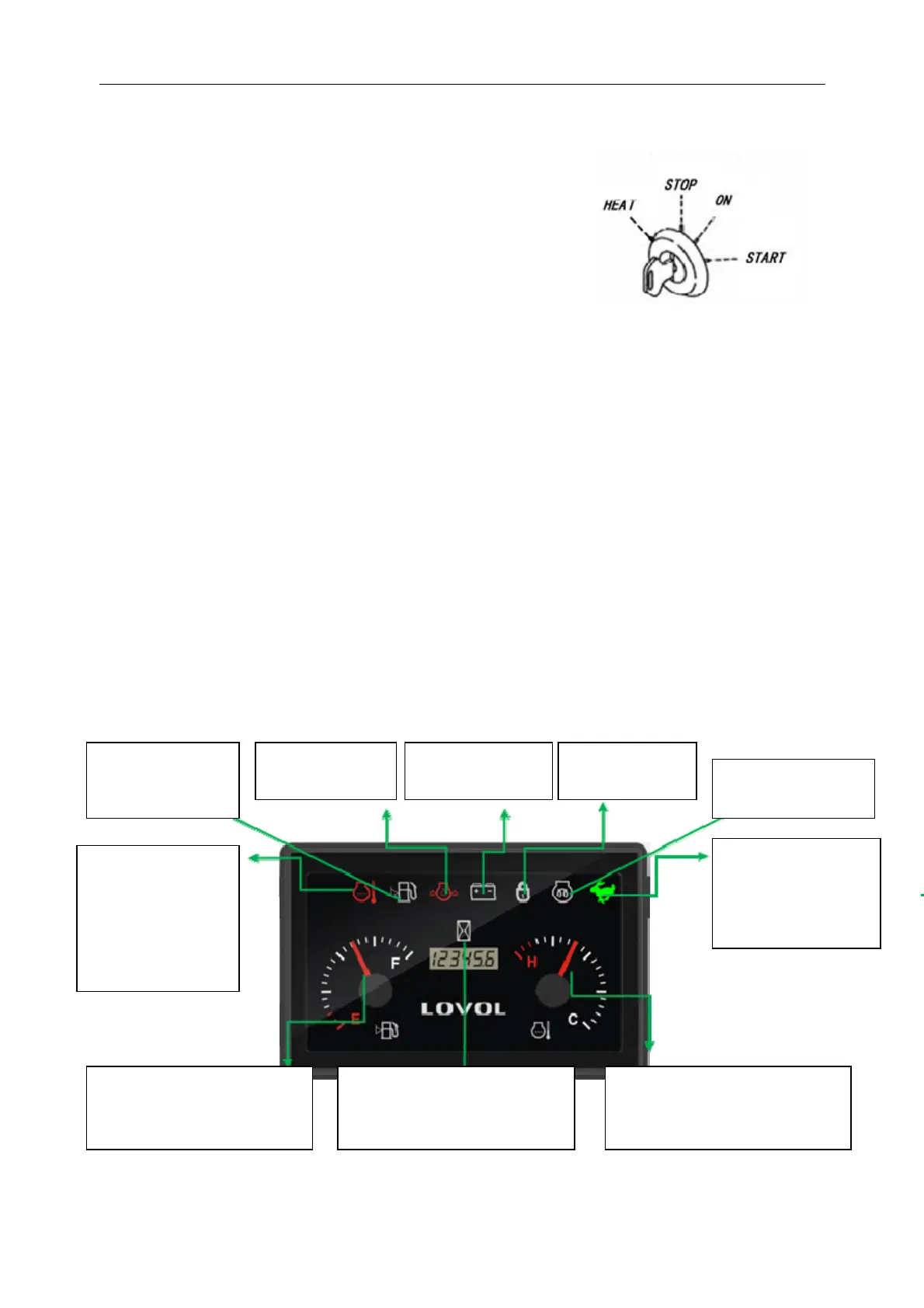
1. Start Switch
The key can be inserted at the
STOP location.
If you turn one gear to the "HEAT" position from the "STOP"
position to the left an d don't let go o f the "HEAT" p osition,
conduct preheating and electric heating display.
If you turn one gear to the right from the STOP position
to the ON position, all circuits will be ON.
"START" if you turn the key from the "ON" (turn ON) position to the "START" position, the starting
motor will rotate and the engine will START. When released, the key will automatically return to the
"ON" (connect) position, so when the engine starts, remove your hand from the key.
IMPORTANT
When starting the en gine, b e sure to put the operating handle lock lever in the "lock" position. If in the
"release" position, the engine will not sta rt.
If a metal key chain is attached to the attached key, it will in terfere with the signal transmission between
the key and the switch, thus causing theenginetofailtostartproperly.
2. Instrumented function
If the picture used in the specification is not in conformity with the real object, please refer to the real
object.
Theiconflasheswhen
the cooling water
temperature is ≥
99 ℃ ,andtheiconis
bright when the
cooling water
temperature is ≥
103℃.
Fuel level ≤1/8 when
the icon lights up
and gives an alarm.
Oil pressure signal
alarm i con long
When charging
signal alarm icon is
When GPS
signal alarm icon
Fuel oil level stepper motor trend
display, display range 0 ~ 8/8,
redzonerange0~1/8
Hour meter display, range 0 ~
99999.9h, accuracy 0.1h. Timing
condition: normal oil pressure or
normal charging.
The cooling water temperature
stepper motor trend display, display
range 40 ℃ ~ 120 ℃ ,redzone
range 103℃ ~ 120℃
Preheating signal
preheating when the
icon is lon
bri
ht.
When walking at high
speed and low speed
signal with high speed,
theiconwillbelong
and bright.
Start Switch