LPKF Laser & Electronics AG | V. 1.0
3.7 Displays and control elements
This chapter describes the displays and control elements of the system. First of all,
make yourself familiar with the individual components of the system before starting the
operation.
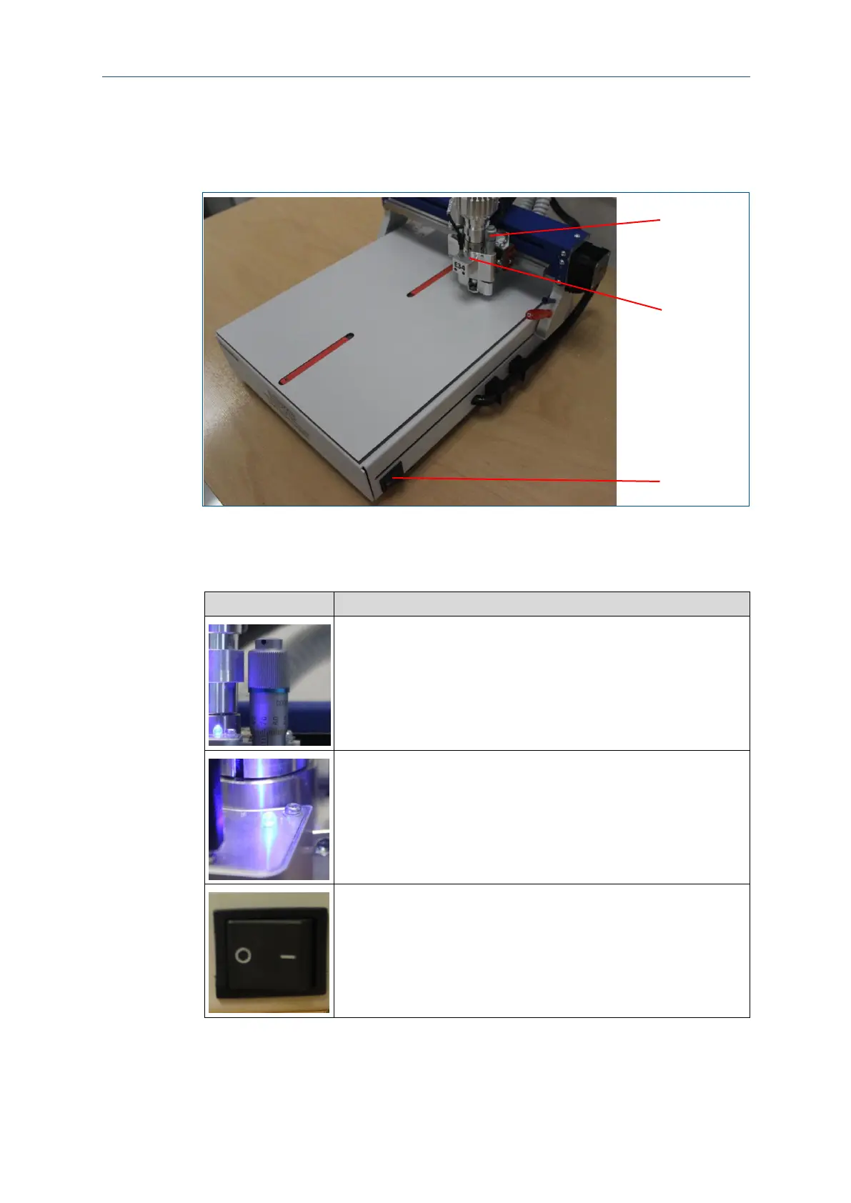
Fig. 7: Displays and control elements
1 Milling-depth adjustment
2 Operation LED
The milling-depth adjustment can be set with the micrometer screw (1),
it defines the height of the processing head when milling the toolpaths.
The operation LED (2) displays the operating state of the system. The
following operating states are displayed at the signal light:
Lit: The system is ready for operation or in operation. No fault exists.
Not lit: The system is not ready for operation because it is switched off
or a fault has occurred.
The On/Off switch (3) switches the power supply on or off.
Table 4: Displays and control elements