RS-485 Communication Features
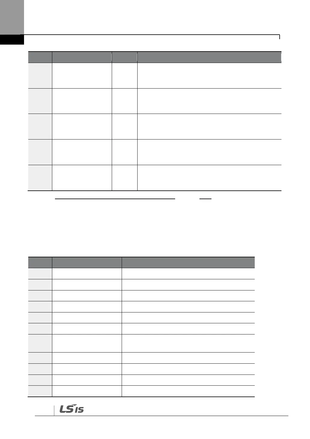
‗Latch‘ type fault trip information 2
(Refer to Common Area parameter address
0h0331)*
‗Latch‘ type fault trip information 3
(Refer to Common Area parameter address
0h0335)*
‗Level‘ type fault trip information
(Refer to Common Area parameter address
0h0332)(1)
H/W Diagnosis fault trip information
(Refer to Common Area parameter address
0h0333)(1)
Warning information
(Refer to Common Area parameter address
0h0334)(1)
* Refer to 7.3.8Compatible Common Area Parameteron page 370.
7.5.3.4 Binary Input
Metasys-N2 master unit monitors the inverter input and output status in binary codes. The
following table lists the binary codes used and their meanings.
1 – Forward operation is running.
1 – Reverse operation is running.
1 –Running at a steady speed (frequency
refernece)
1 – Running on DC power source
1–Stopping is in progress.


 To Next Page