Chapter 4. Basic Features
24
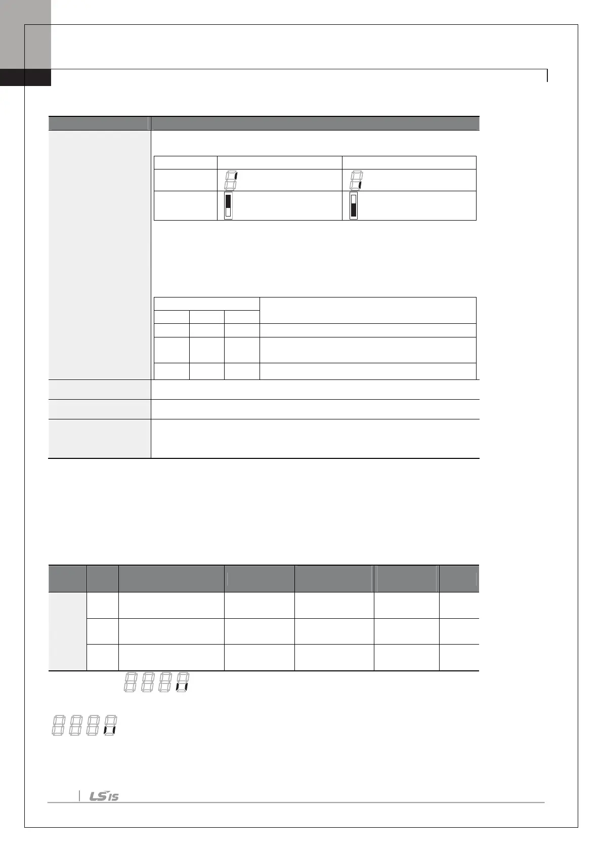
Fault Trip Output by Multi-function Output Terminal and Relay - Setting Details
OU.30 Trip Out Mode
Fault trip relay operates based
on the fault trip output settings.
Select fault trip output terminal/relay and select 29(Trip Mode) at codes OU.
34, 35. When a fault trip occurs in the inverter, the relevant terminal and relay
will operate. Depending on the fault trip type, terminal and relay operation
can be configured as shown in the table below.
Operates when low voltage fault trips occur
trips other than low voltage
occur
Operates when auto restart fails (Pr. 08–09)
OU.34 Relay3 Set relay output (Relay 3).
OU.35 Relay4 Set relay output (Relay 4).
OU.53 TripOut On Dly,
OU.54 TripOut OffDly
If a fault trip occurs, trip relay or
function output operates after the time
delay set in OU.53. Terminal is off with the input initialized after the time delay
set in OU.54.
4.4.3
Multi-function Output Terminal Delay Time Settings
Set on-delay and off-delay times separately to control the output terminal and relay operation times. The delay
time set at codes OU.50–51 applies to multi-function output terminal (Q1), relay (Relay 1, 3, 4), except when the
multi-function output function is in fault trip mode.
Group
Code
Name LCD Display
Setting
Range
Unit
OU
50
On delay
DO On Delay 0.00
0.00–100.00
s
51
Off delay
DO Off Delay 0.00
0.00–100.00
s
52
output terminal
DO NC/NO Sel
00*
00–11
bit
* Displayed as on keypad. On the 7-seg screen of multi-function output contact
parameter, clicking of left/right key switches between extension I/O and built-in I/O 7-seg screen.
is extension I/O 7-seg screen.

 Loading...


