Chapter 3. Installation
8
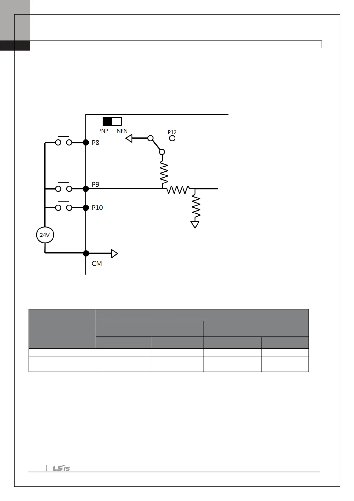
▪ PNP Mode (Source)
Select PNP using the PNP/NPN selection switch (SW1). Note that the factory default setting is NPN mode. CM is
is the common ground terminal for all analog inputs at the terminal, and P12 is 12V internal source. If you are
using an external Voltage source, build a circuit that connects the external source (-) and the CM terminal In case
of PNP, you should apply more than 3V source for on-state and less than 2V for off-state.
3.3 Signal (Control) Cable Specifications
Terminals
Signal Cable
Without Crimp Terminal Connectors
(Bare Wire)
With Crimp Terminal Connectors
(Bootlace Ferrule))
mm2 AWG mm2 AWG
A4/B4/C4
1.0 17 1.5 15

 Loading...


