Chapter 4. Basic Features
17
25
I4 output at minimum
current (%)
I4 Perc y1 0.00
0–100
%
26
I4 maximum input current
I4 Curr x2 20.00
0.00–24.00
mA
27
I4 output at maximum
current (%)
I4 Perc y2 100.00
0.00–100.00
%
28
I4 rotation direction options
I4 Inverting 0 No
0–1
-
I4 Quantizing level
* Quantizing is disabled if ‘0’ is selected.
Input Current (I4) Setting Details
In.01 Freq at 100%
Configures the frequency reference for operation
the maximum current (when
Ao.27 is set to 100%).
• If In.01 is set to 40.00Hz, and default settings are used for Ao.24–27, 20mA
input current (max) to I4 will produce a frequency reference of 40.00Hz.
• If Ao.27 is set to 50.00 (%), and default settings are used for In.01 (60Hz) and
Ao.24–26, 20mA input current (max) to I4 will produce a frequency reference
of 30.00Hz (50% of 60Hz).
Used to monitor input current at I4.
Ao.23 I4 Filter
Configures the time for the operation frequency to reach 63% of target
frequency based on the input current at I4.
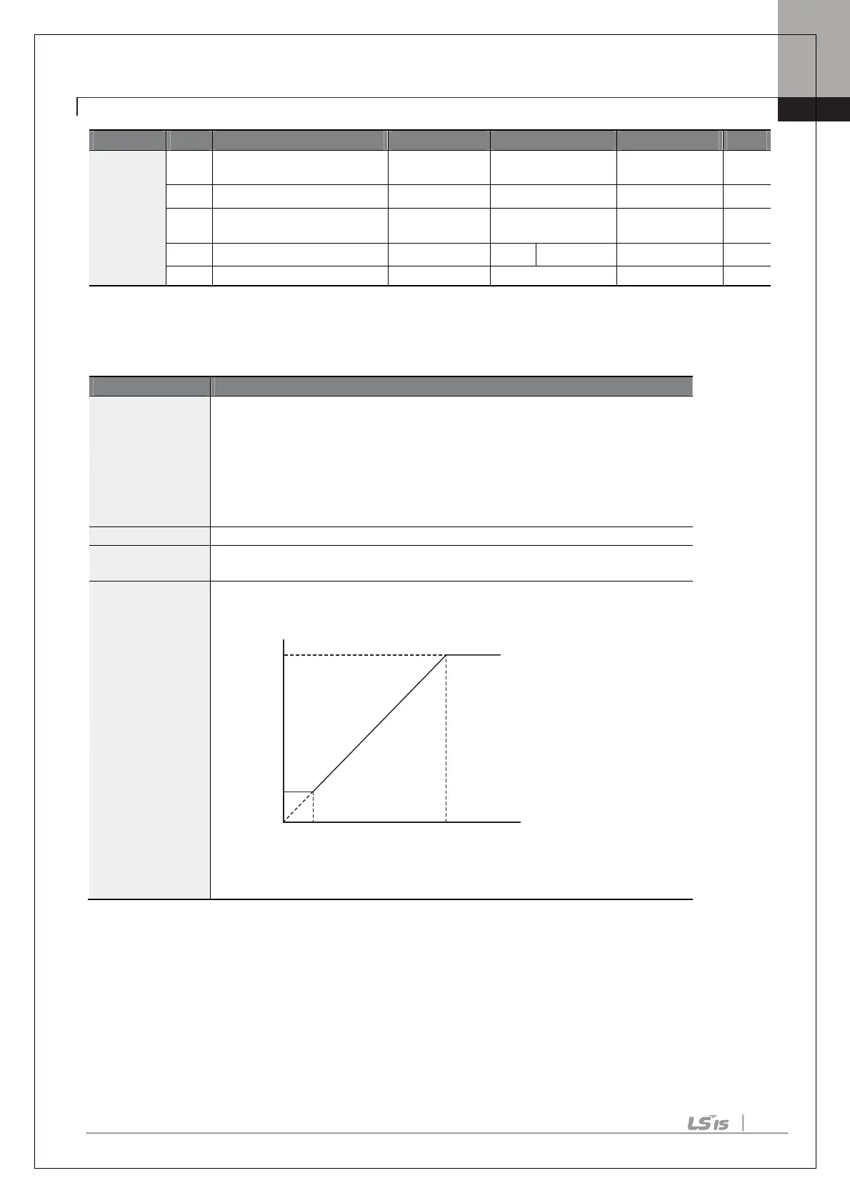
In.24 I4 Curr x1–
In.27 I4 Perc y2
Configures the gradient level and off
set value of the output frequency.
[Gradient and off-set configuration based on output frequency]
4.2.2 Setting a Frequency Reference with Input Voltage (Terminal I4)
Set and modify a frequency reference using input voltage at I4 (V4) terminal by setting SW2 to V4. Set the Frq
(Frequency reference source) code in the Operation group to 15 (V4) and apply 0–12V input voltage to I4 (=V4,
Analog current/voltage input terminal). Codes Ao.14–21 will not be displayed when I4 is set to receive current
input (Frq code parameter is set to 16).
I4
Ao.26
Ao.24
Ao.25
Ao.27
Frequency Reference
input

 Loading...


