Chapter 4. Basic Features
16
Rotational Directions for Different Voltage Inputs
Command /
Voltage Input
0–10V -10–0V
-10–10V Voltage Input Setting Details
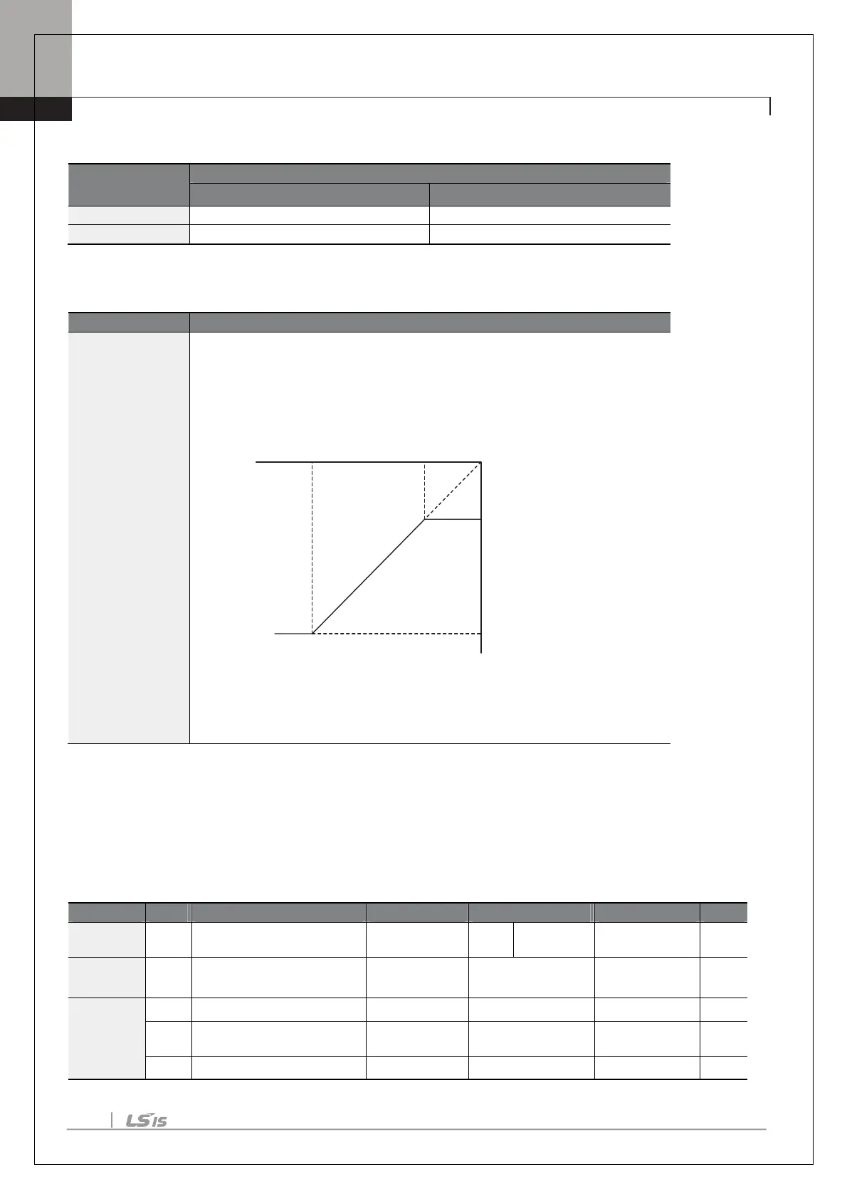
Ao.10 V3- volt x1–
Ao.13 V1- Perc y2
Sets the gradient level and off
set value of the output frequency in relation to the
input voltage. These codes are displayed only when Ao.02 is set to 1 (bipolar).
As an example, if the minimum input voltage (at V3) is set to -2 (V) with 10%
output ratio, and the maximum voltage is set to -8 (V) with 80% output ratio
respectively, the output frequency will vary within the range of 6 - 48 Hz.
[Ao.10 V3-volt X1–Ao.13 V3 Perc y]
For details about the 0–+10V analog inputs, refer to the code descriptions Ao.10
V3 volt x1–Ao.13 V1 Perc y2..
Setting a Reference Frequency using Input Current (I4)
You can set and modify a frequency reference using input current at the I4 terminal after selecting current input
at SW 2. Set the Frq (Frequency reference source) code in the Operation group to 16 (I4) and apply 4–20mA
input current to I4.
Operation Frq
Frequency reference
source
Freq Ref Src 16 I4
0–16
-
In 01
Frequency at maximum
analog input
Freq at 100% 60.00
0– Maximum
Frequency
Hz
Ao
22
I4 input monitor
I4 Monitor 0.00
0.00–24.00
mA
23
I4 input filter
time constant
I4 Filter 10
0–10000
ms
24
I4 minimum input current
I4 Curr x1 4.00
0.00–20.00
mA
Ao.12 Ao.10
Ao.11
-8V -2V
6Hz
48Hz
Ao.13
V3 input
Frequency reference

 Loading...


