Chapter 4. Basic Features
29
4.8 Multi-function Input Terminal Control
Filter time constants and the type of multi-function input terminals can be configured to improve the response
of input terminals
p
Code
Name LCD Display
Setting
Setting Range Unit
In
terminal On filter
0–10000
terminal Off filter
0–10000
terminal selection
terminal status
* Displayed as on the keypad. On the 7-seg screen of multi-function input
state/contact parameter, clicking of left/right key switches between extension I/O and built-in I/O 7-seg
screen. is extension I/O 7-seg screen.
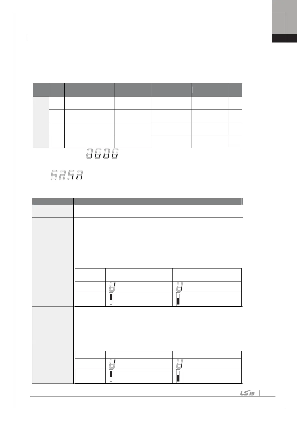
Multi-function Input Terminal Control Setting Details
In.86 DI Off Delay
s state is not changed during the set time, when the terminal
receives an input, it is recognized as On or Off.
In.87 DI NC/NO Sel
Select terminal contact types
for each input terminal. The position of the
indicator light corresponds to the segment that is on as shown in the table below.
With the bottom segment on, it indicates that the terminal is configured as a A
terminal (Normally Open) contact. With the top segment on, it indicates that the
terminal is configured as a B terminal (Normally Closed) contact. From right to left
side, there are P1~P7 terminals. In case of installation of extension I/O, P8/P9/P10
terminals are added.
B terminal status (Normally
Closed)
A terminal status (Normally
Open)
In.90 DI Status
Display the configuration of each contact. When a segment is configured as A
terminal using dr.87, the On condition is indicated by the top segment turning on.
The Off condition is indicated when the bottom segment is turned on. When
contacts are configured as B terminals, the segment lights behave conversely.
From right to left side, there are P1~P7 terminals. In case of installation of
extension I/O, P8/P9/P10 terminals are added.

 Loading...


