Chapter 4. Basic Features
20
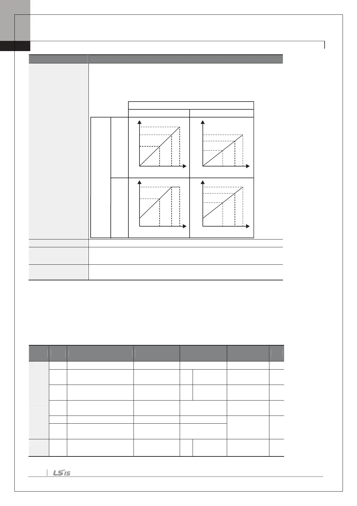
Example, if the maximum frequency set at dr.20 (Max Freq) is 60Hz and the
present output frequency is 30Hz, then the x-axis value on the next graph is
50%.
et filter time constant on analog output.
AO.34 A013Const %
Mode) is set to 15(Constant), the analog
voltage output is dependent on the set parameter values (0–100%).
AO.35 AO3 Monitor
onitors analog output value. Displays the maximum output voltage
percentage (%) with 10V as the standard.
4.4 Digital Output
4.4.1 Multi-function Output Terminal and Relay Settings
Group
Code
Name LCD Display
Setting
Setting Range
Unit
OU
34
setting
Relay 3 29 Trip - -
35
setting
Relay 4 29 Trip - -
41
monitor
DO Status - 00– 11 bit
0.00–Maximum
frequency
Hz
58
band
FDT Band 10.00
In
65–
74
Px terminal configuration
Px Define 16 Exchange - -
0%
50% 80% 100%
10V
8V
5V
0%
50% 80% 100%
8V
6.4V
4V
0%
50% 80% 100%
10V
7V
2V
0%
50% 80% 100%
10V
8.4V
2V
6V
Ao.31 AO3 Gain
100.0%
0.0%
Ao.32
AO3 Bias
20.0%
80.0%(Factory default)
Factory
default

 Loading...


