Chapter 4. Basic Features
21
*Displayed as on the keypad.
Multi-function Output Terminal and Relay Setting Details
OU.41 DO Status
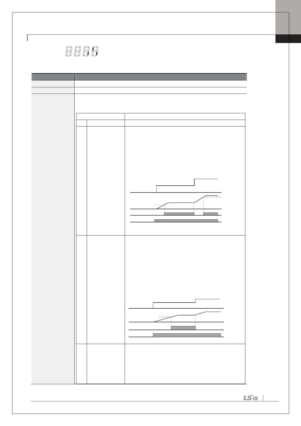
et output terminal and relay functions according to OU.57 FDT (Frequency),
OU.58 (FDT Band) settings and fault trip conditions.
Detects inverter output frequency reaching
frequency. Outputs a signal when the absolute value
(set frequency–output frequency) < detected frequency
width/2.
When detected frequency width is 10Hz, FDT-1 output
is as shown in the graph below.
detected frequency (FDT Frequency) are equal, and
fulfills FDT-1 condition at the same time.
[Absolute value (set frequency-detected frequency) <
detected frequency width/2]&[FDT-1]
Detected frequency width is 10Hz. When the detected
frequency is set to 30Hz, FDT-2 output is as shown in
the graph below.
frequency–operation frequency) < detected frequency
width/2.
Detected frequency width is 10Hz. When detected
frequency is set to 30Hz, FDT-3 output is as shown in
Q1
15Hz
20Hz
20Hz
40Hz
40Hz
35Hz
Frequency
reference
Operation
Frequency
Run cmd
Q1
25Hz
30Hz
50Hz
Frequency
reference
Frequency
Run cmd

 Loading...


