Chapter 4. Basic Features
22
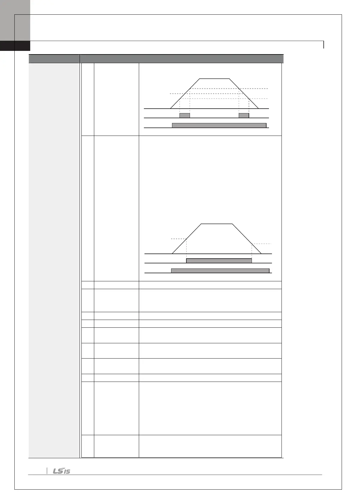
Output signal can be separately set for acceleration and
deceleration conditions.
• In acceleration: Operation frequency≧ Detected
frequency
• In deceleration: Operation frequency>(Detected
frequency–Detected frequency width/2)
Detected frequency width is 10Hz. When detected
frequency is set to 30Hz, FDT-4 output is as shown in
the graph below.
signal when a fault is triggered from
protective function operation by inverter overload
inverse proportion.
stalled.
inverter DC link voltage rises
above the protective operation voltage.
drops below the low voltage protective level.
terminal and RS-485 communication command at the
terminal block.
Outputs a signal when communication power and
expansion an I/O power card is installed, and also
outputs a signal when losing analog input and
communication power commands.
signal when operation command is entered
and the inverter outputs voltage.
No signal output during DC braking.
30Hz
35Hz
25Hz
Q1
Frequency
Run cmd
30Hz
25Hz
Q1
Frequency
Run cmd

 Loading...


