Chapter 2. Specifications
3
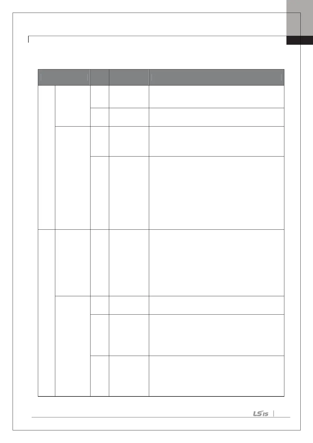
2.2 Input and Output Specification
Function Label
Name Description
IN
PUT
Multi-
function
terminal
configuration
P8 ~
P10
Multi-function
Input 8~10
Configurable for multi-function input terminals.
CM
Common
Sequence
Common terminal for analog terminal inputs and outputs.
Analog input
configuration
V3
Voltage input
for frequency
reference input
Used to setup or modify a frequency reference via analog
voltage input terminal.
• Unipolar: 0–10V (12V Max.)
• Bipolar: -10–10V (±12V Max.)
I4
Voltage/current
input for
frequency
reference input
Used to setup or modify a
frequency reference via analog
voltage or current input terminals.
Switch between voltage (V4) and current (I4) modes using a
control board switch (SW2).
V4 Mode:
• Unipolar: 0–10V (12V Max.)
I4 Mode
• Input current: 4–20mA
• Maximum Input current: 24mA
• Input resistance: 249Ω
OUT
PUT
Analog
Output
AO3
Voltage/Curren
t Output
devices: output frequency, output current, output voltage,
or a DC voltage.
Operate switch (SW3) to select the signal output type
(voltage or current) at the AO terminal.
Output Signal Specifications:
• Output voltage: 0–10V
• Maximum output voltage/current: 12V/10mA
• Output current: 0–20mA
• Maximum output current: 24mA
• Factory default output: Frequency
Digital
Output
CM
Common
Sequence
Common terminal for analog terminal inputs and outputs.
A3,
C3,
B4
Fault signal
output
Sends out alarm signals when the inverter’s safety features
are activated (AC 250V <1A, DC 30V < 1A).
Fault condition: A3 and C3 contacts are connected (B3 and
C3 open connection)
Normal operation: B3 and C3 contacts are connected (A3
and C3 open connection)
A4,
C4,
B4
Fault signal
output
Sends out alarm signals when the inverter’s safety features
are activated (AC 250V <1A, DC 30V < 1A).
Fault condition: A4 and C3 contacts are connected (B4 and
C4 open connection)
Normal operation: B4 and C4 contacts are connected (A4
and C4 open connection)

 Loading...


