Chapter 4. Basic Features
18
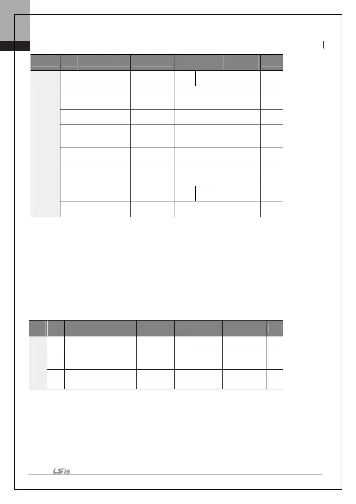
Group Code
Name LCD Display
Setting
Range
Unit
Operation
Frq
reference source
Freq Ref Src 15 V4 0–16 -
Ao
15
constant
V4 Filter 10 0–10000 ms
16
voltage
V4 Volt x1 0.00 0.00–10.00 V
17
minimum V4
voltage
V4 Perc y1 0.00 0.00–100.00 %
18
voltage
V4 Volt x2 10.00 0.00–10.00 V
19
maximum V4
voltage
V4 Perc y2 100.00 0.00–100.00 %
20
direction
V4 Inverting 0 No
0–1
-
21 V4 quantizing level V4 Quantizing 0.04
10.00
%
* Quantizing is disabled if ‘0’ is selected.
4.3 Analog Output
An analog output terminal provides output of 0–10V voltage, 4–20mA current.
Voltage and Current Analog Output
An output size can be adjusted by selecting an output option at AO3(Analog Output3) terminal. Set the analog
voltage/current output terminal setting switch (SW3) to change the output type (voltage/current).
p
Code
Name LCD Display
Setting
Setting Range Unit
Ao
33 Analog output3 filter AO3 Filter 5
0–10000
ms
34 Analog constant output3 AO3 Const %
0.0
0.0–100.0
%
35 Analog output3 monitor AO3 Monitor 0.0
0.0–1000.0
%

 Loading...


