Chapter 4. Basic Features
26
Multi-step Frequency Setting Details
St 1–St3
Step Freq - 1–3
If an LCD keypad is in use, bA.50–52 is used instead of St1–St3 (multi-step
frequency 1–3).
bA.53–56
Step Freq - 4–7
Configure multi-step frequency 4–7.
In.72–74 Px Define
Choose the terminals to setup
step inputs, and then set the
codes (In.72–74) to 7(Speed-L), 8(Speed-M), or 9(Speed-H).
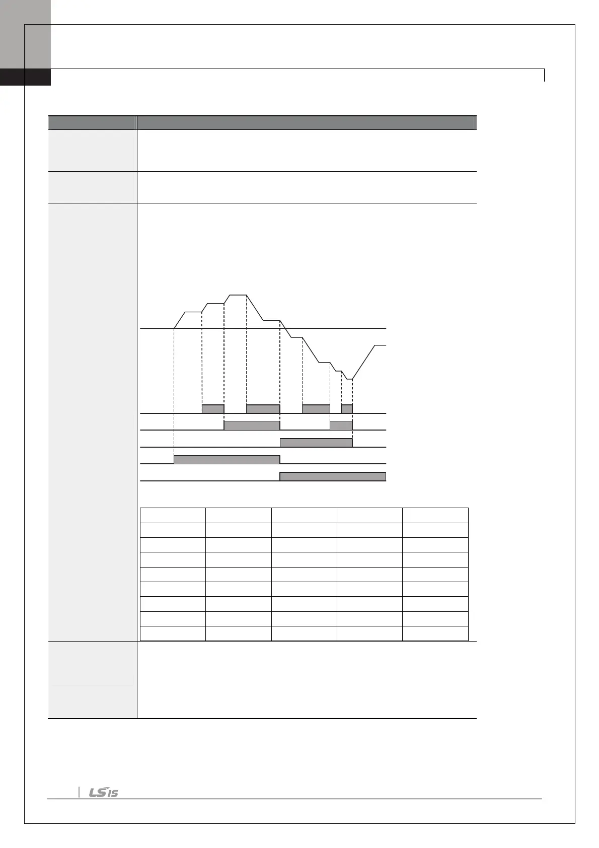
Provided that terminals P3, P4 and P5 have been set to Speed-L, Speed-M and
Speed-H respectively, the following multi-step operation will be available.
[An example of a multi-step operation]
Speed Fx/Rx P5 P4 P3
0 - - -
1 - -
2
-
-
3
-
4
- -
5
-
6
-
7
In.89 InCheck Time
time interval for the inverter to check for additional terminal block inputs
after receiving an input signal.
After adjusting In.89 to 100ms and an input signal is received at P8, the inverter
will search for inputs at other terminals for 100ms, before proceeding to
accelerate or decelerate based on P8’s configuration.
P8
P9
P10
RX
FX
Step 0
1
2
3
4
5
6
7
0

 Loading...


