Lucent Technologies Lineage
®
2000 ECS/GPS Battery Plant J85500G-2
4 - 8 Installation Issue 6 May 1999
acceptance testing procedures for the CP5 circuit pack and the
associated LVD/R option.
AC wiring,
rectifier
installation & test
Refer to the installation and start-up procedure in the Rectifier
manual for the following steps.
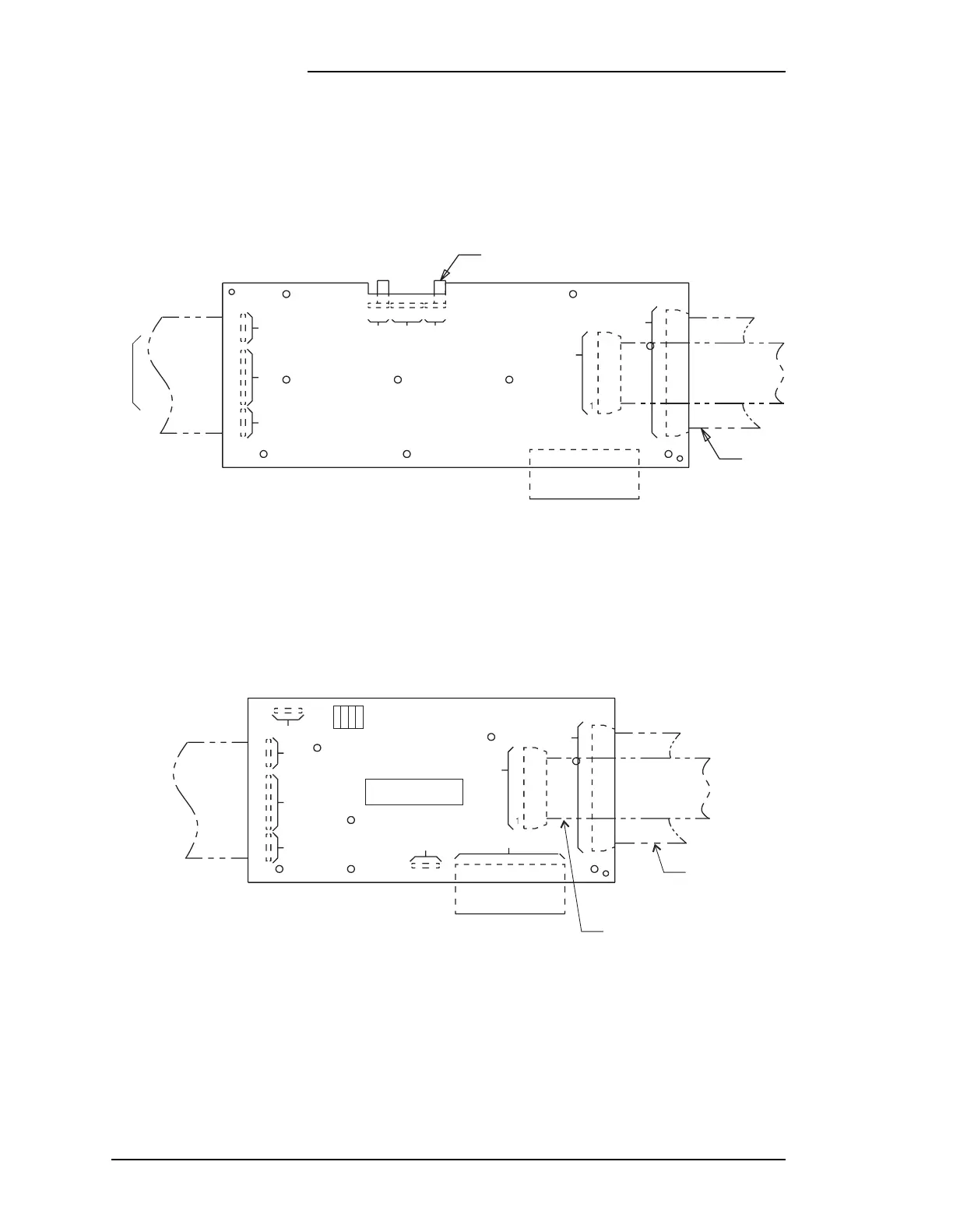
Figure 4-3: LVD/fuse board (CP5) jumper locations
GENERAL
PATH OF
WIRE
SET
TO PLANT
BUS BARS
4
1
1
1
3
8
P506
P505.2
LVD/FUSE BOARD
BCB2
(CIRCUIT SIDE)
331115
P507 P505.1
P508
TB501
12 1
20
P502
40
1
P501
P504
JUMPERS
GENERAL PATH
OF 846651051
RIBBON CABLE
Figure 4-4: LVD/fuse board with thermal compensation circuitry (BMD1) switch locations
GENERAL
PATH OF
WIRE SET
4
1
10
1
5
6
1
1
3
8
P506
P507
P510
TB501
BMD1
SD-82673-02
P508
TB501
GENERAL PATH OF
846651040
RIBBON CABLE
GENERAL PATH OF
846651051
RIBBON CABLE
TO PLANT
CONTROLLER
TO PLANT
BUS BARS
12
12
1
1
20
P502
40
1
P501
P504
41
SW500