Lucent Technologies Lineage
®
2000 ECS/GPS Battery Plant J85500G-2
4 - 18 Installation Issue 6 May 1999
approximately the same time that the yellow LED on the
216A Control Unit is turned on which should correspond
to a two-volt drop in the float voltage.
A major fuse alarm (MJF) should be issued at the same
time as the yellow LED on the 216A Control Unit begins
blinking. The six-volt drop will not be seen because the
batteries will not discharge that quickly.
6. Allow the thermistors to cool, then insert and secure them
into the battery string.
7. Verify that no alarms are present at this time.
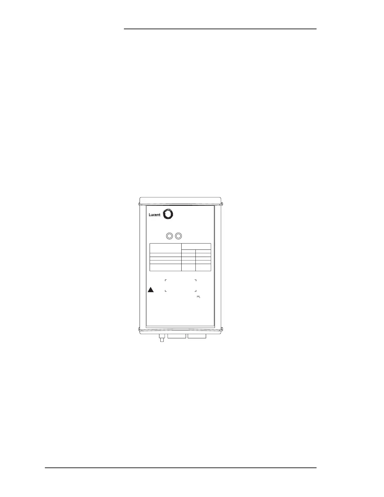
Figure 4-5: 216A Battery Thermal Compensation Control Unit faceplate
BATTERY
THERMAL
COMPENSATION
MODULE
216A CNTL MOD
YEL
INDICATOR
STATUS
GREEN
MODULE
CONDITION
NORMAL
TEMP > 53 C°
TEMP > 73 C°
NO THERMISTORS
CONNECTED
INPUT: P511, P512 (2) & (3), UP TO 12V
LIMITED TO 15 mA NEC CLASS 2.
P511, P512 (1), (4), (5), & (9)
LESS THAN 60 VDC,
FUSED AT 1 1/3 AMPERES.
MEASUREMENT: TB101 & 102 TEMPERATURE
LAMP TEST
847586807
CLEI:
ON
ON ON
FLASH
OFFOFF
ON
YELLOW
OFF
GRN
INDICATORS
!