A3-10 Issue 1 November 1998
363-208-011, Appendix 3
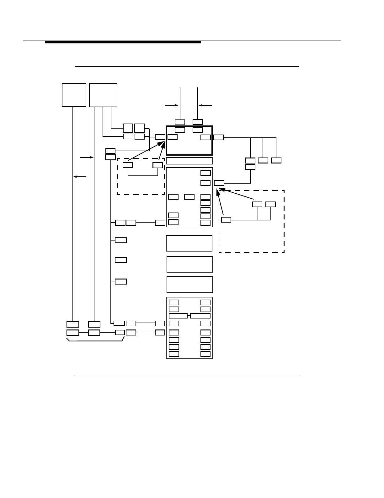
Test Head Installation
Figure 1-1. Test Head System Interconnections
P171
J175
J130
J131
J132
J133
ARM/UIP
MDS 4
MDS 3
MDS 2
P106
P206
J501
P101
P102
P103
P104
P105
P205
J500
P201
P202
P203
P204
ED7C723-32
P301
P501
Backplane
Fuse Panel
MDS 1
FAN
ED7C723-30
P275 P175
J301-1
J301-2
J301-3
J301-4
TAP to ARM/MDS
J275
J301
ED7C723-34 Group 1
P301
P256
P266
E1-E4
Misc. DF
J101
ED7C723-32
P101
J101
J44
P44
955-7000010108
P13
J13
RS232 Control Link
Tau-tron
ngRTH*
Test Head
J15
J12
P15
P12
FDI
VF Interface
ED7C723-35
G-1, 2, or 3
P101A P101B
ED7C723-34 G13
J101A J101B
VF Pairs
ED7C723-35
G-1, 2, or 3
G10
G2
G7
P14
Monitor
MLT
J183
MTAU
MTAU
J14
955-7000000037
955-7000107
TL1
Alarms
Talk
955-700079
Note:
The cables with numbers that begin with
955- are provided by Tau-tron.
955-7000000038
955-7000XXX126
Monitor
MLT
Talk
955-7000XXX126
Battery Supply
Ringing Supply
P44
J44
ED7C723-37, G 30
P37
Note:
The ED7C723-37, G 30 cable assembly is required
when multiple COTs are inter-connected to obtain
SONET/DS1 timing and the Tau-tron test head
needs access to J44.
To Adjacent
SLC
-2000 COT
* ngRTH is a trademark of General Signals Corporation
Lucent Technologies RTH-7000
J14
955-7000003046
P14
Note:
The 955-7000003046 cable assembly
test head to the front of the frame.
is provided to bring access to J14 of the
955-7000XXX036
or