2-16 Issue 4 February 1997
363-208-011
Installation Procedures
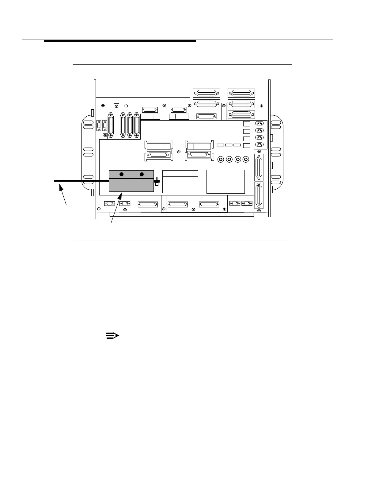
Figure 2-6. PIU Mounting Details
J1C265AD-1 ARM Shelf Mounting Procedure
Step 1:
Mount the shelf and its associated baffle panel, using their attached
hardware, to their designated bay positions.
Step 2:
Locate the ground strap attached to the ARM shelf and connect it to the
bay frame as indicated in Figure 2-5.
Step 3:
Locate the ground strap attached to the UIP ESD jack and connect it to
the bay frame as indicated in Figure 2-5.
NOTE:
Remove any paint as necessary on the bay frame to ensure a
low-resistance contact.
Step 4:
Move the attached shelf cable assemblies forward so that they drape
into the bay frame’s cable duct areas. Leave the connectors in place at
this time for future connection to the Intrabay and Customer Interface
cable assemblies.
-48V B
-48V A
-48V RTN B
-48V RTN A
E 1
E 2
E 3
E 4
J43 J42 J39 J38
J166
J162
J165
J163
J183
J167
J182
J168
J174
J177
J175
J172
J173
P170
J176
P171
J179
J184 J161 J160 J45 J50
J53
J37
J44
J133
J131
J130
J132
CONNECTOR LABELS
SEE FIGURE LABELS
SEE CONNECTOR
FIGURE
ARM Shelf (Rear View)
DS1 OUT 17-28
DS1 DISTRIBUTION
DS1 OUT 1-16
DS1 IN 17-28
DS1 IN 1-16
DS1 OUT 17-28
DS1 OUT 1-16
DS1 IN 17-28
DS1 IN 1-16
PIU
Cable
Assembly