363-208-011
Installation Procedures
Issue 4 February 1997 2-19
NOTE:
Remove any paint as necessary on the bay frame to ensure a
low-resistance contact.
Step 4:
Move the attached shelf cable assemblies forward so that they drape
into the bay frame’s cable duct areas. Leave the connectors in place at
this time for future connection to the Intrabay and Customer Interface
cable assemblies.
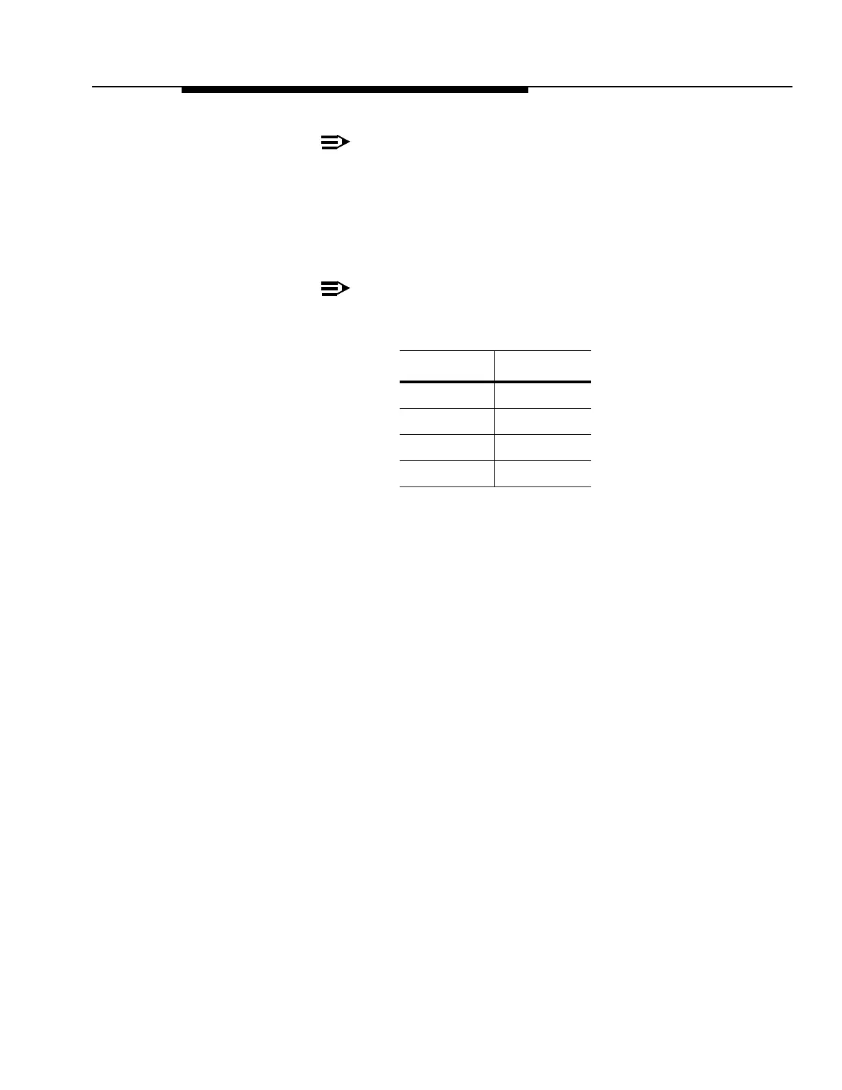
NOTE:
The following connectors on the shelf dangler cables should be
visible in their respective (rear view) ducts:
Left Duct Right Duct
P114 J173
P115 P183
J115
P184