2-18 Issue 4 February 1997
363-208-011
Installation Procedures
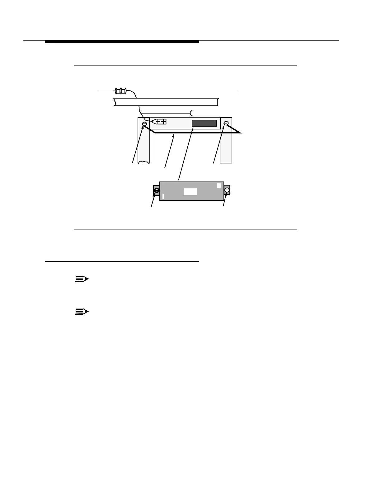
Figure 2-7. TS1 Terminal Block Location
1A Alarm and Test Unit Installation
NOTE:
Only one 1A ATU Shelf is required for the COT Bay. The shelf must be
located at the specific location depicted in Figure 2-5.
NOTE:
For a front extended mount application the shelf's flanges must be
removed and relocated to line up with the adjacent shelves.
Mounting Procedure
Step 1:
Open the carton and inspect the shelf and all its connectors and cable
assemblies for damage or misalignment.
Step 2:
Mount the shelf using its attached hardware to its designated bay posi-
tion.
Step 3:
Locate the ground strap attached to the ATU shelf and connect it to the
bay frame as indicated in Figure 2-5.
Framework (Rear View)
Provided with Bay Frame
Part of Cable Rack
TS1
1
50
841595184 Terminal
900118266 Screw
900118266 Screw
842094922 Cable Support
840060180 Screw
840060180 Screw
353A