363-208-011
Cabling, Wiring, and Assembly
Issue 4 February 1997 3-11
Shelf Cables Verification
Step 1:
Verify that each shelf has been provided with its standard and optional
cable assemblies and that the connectors have been routed to the
appropriate cable duct (right or left). Refer to the following table and Fig-
ures 3-7 and 3-8.
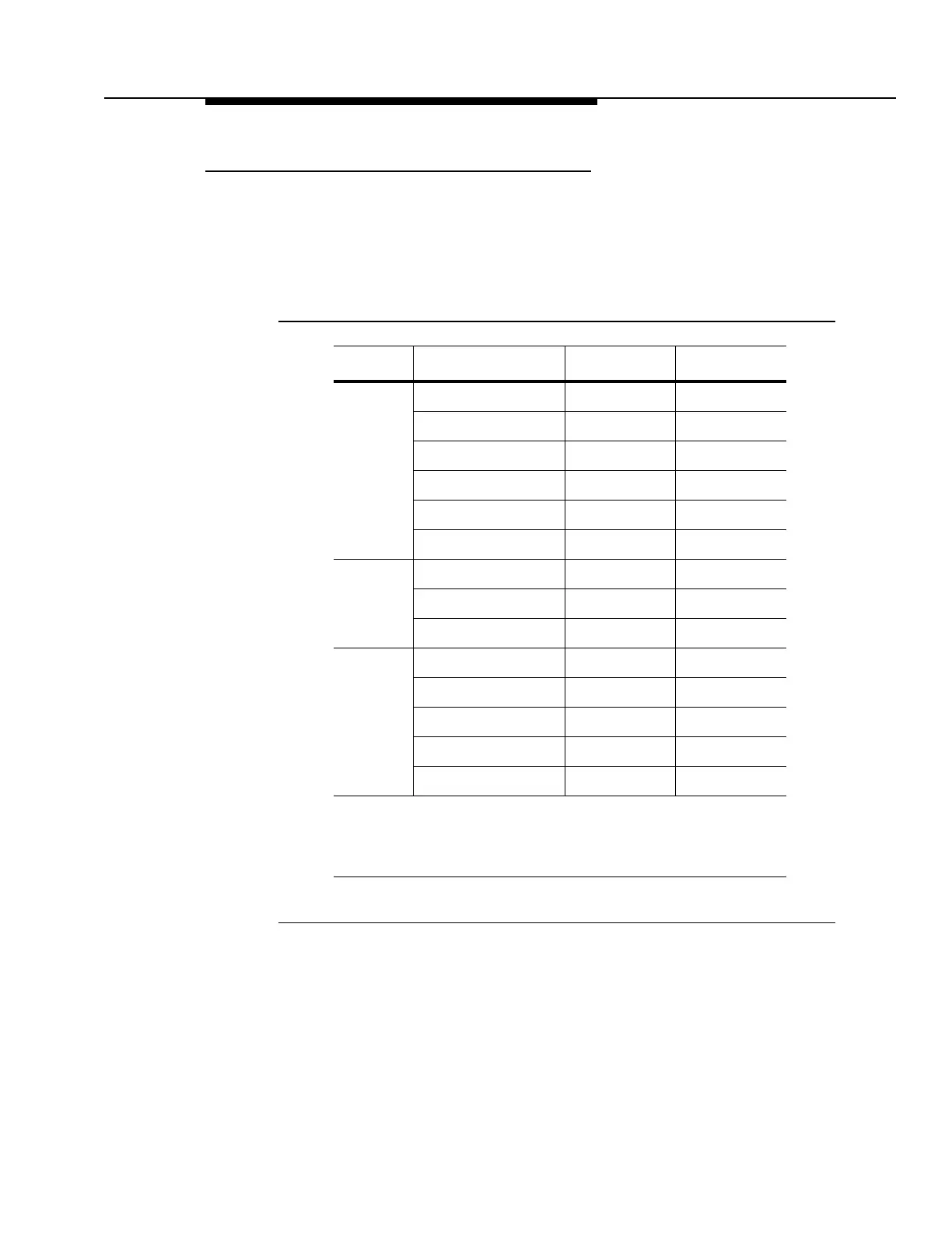
Table 3-1. Cable Verification for ARM and MDS Shelves
Shelf Cable Assembly Left Duct* Right Duct*
ARM ED7C723-30, G6 J303
ED7C723-30, G7 P275
ED7C723-30, G9()** J500-1
ED7C723-30, G10() J500-2
ED7C723-30, G11() J500-3
ED7C723-30, G12() J500-4
MDS ED7C723-32, G1 J302
ED7C723-32, G10 P301
ED7C723-32, G11() P500
ATU ED7C723-36, G1() P114
ED7C723-36, G3() P183
ED7C723-36, G4 J173
ED7C723-36, G5 J115/P115
ED7C723-36, G6 P184
* As viewed from the rear of the bay
** The parenthesis after the group number of the cable assembly
means that there may be an alpha character after the numeric
character, e.g., Group 2 or Group 2A or Group 2B.