3-16 Issue 4 February 1997
363-208-011
Cabling, Wiring, and Assembly
Power and Ringing Local Interfaces
NOTE:
Verify that no
SLC
-2000 Circuit Packs are inserted.
NOTE:
If the Power Interface Unit (ED7C734-30) and the Standard Bay Cable
Assembly [ED7C723-34 Group 2()] have been shipped as two separate
items then it would be more efficient to mate the two pieces before install-
ing in the frame duct. Refer to the INSTALLATION PROCEDURES chapter.
Power Interface Unit/Standard Bay Cable
Connections
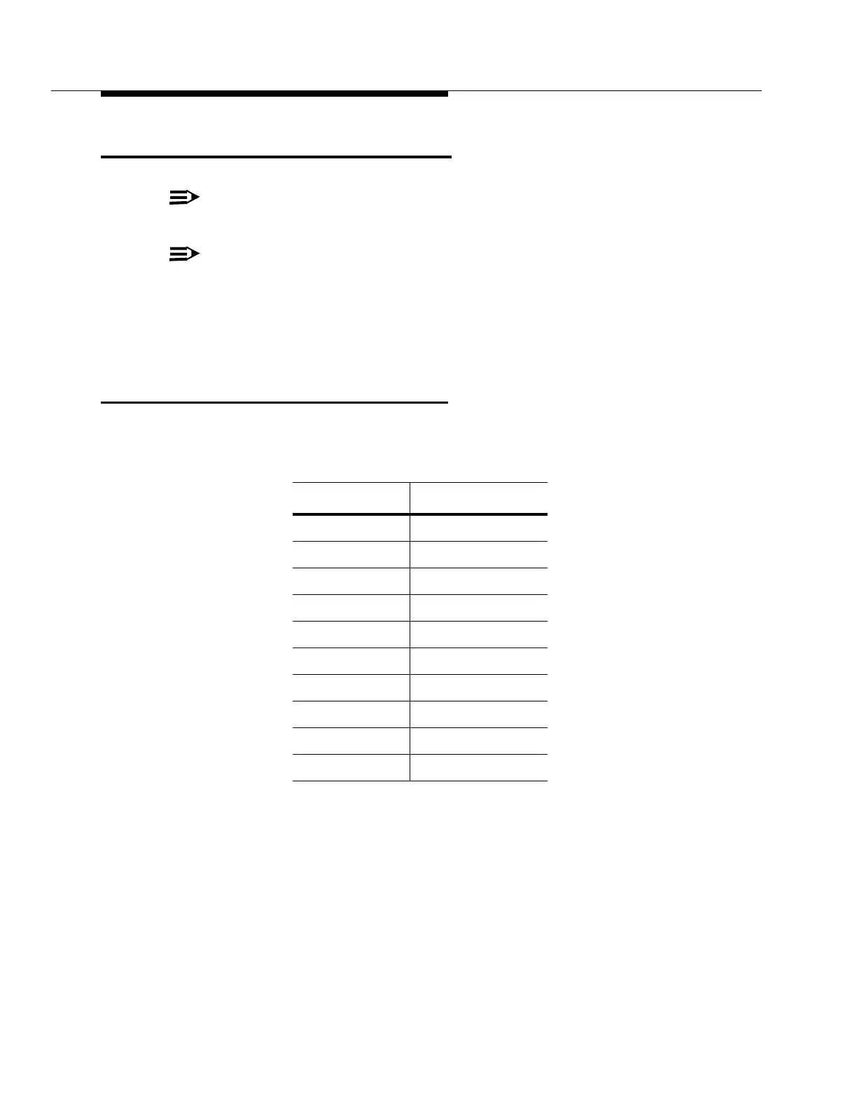
Step 1:
Open the Power Interface Unit and connect/verify the Bay Cable Assem-
bly as follows:
Unit Terminal Cable Color Code
1 R (2 wires)
2 BK (2 wires)
3 R and R-BK
4 BK and BK-R
5 BL-BK (2 wires)
6 W-BL (2 wires)
7 Y-BL (2 wires)
8 O-BK (3 wires)
9 W-O (3 wires)
10 Y-O (3 wires)