3-28 Issue 4 February 1997
363-208-011
Cabling, Wiring, and Assembly
1A Alarm Test Unit Cables
General
NOTE:
The 1A ATU shelf is equipped with several cable assemblies, ED7C723-36
G1(), 3()-6, which interface with other equipment within the COT bay. The
following procedures detail those connections.
ED7C723-36 Group 1 Connections
NOTE:
This procedure consists of mating the ATU Shelf connector to the cable
assembly of the PIU [ED7C723-34 Group ()] which had been installed ear-
lier.
NOTE:
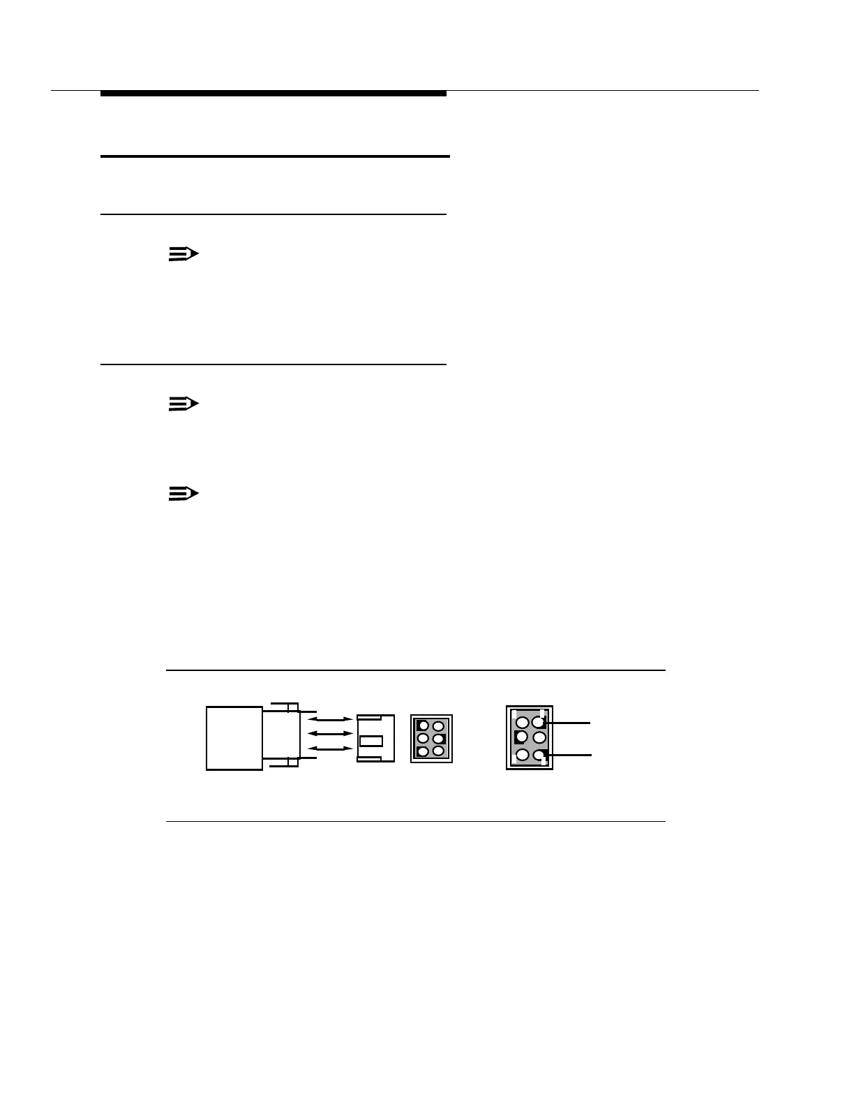
Pin 2 is not assigned. Fan Fail (FANF) lead pin 4 is also not assigned (see
Figure 3-19).
Step 1:
Route the ATU's cable to the left cable duct.
Step 2:
Mate the P114 connector to the J114 connector of the Power Interface
Cable Assembly [ED7C723-34 Group ()] previously installed.
Step 3:
Tie the cable to the ARM Shelf cables in the left cable ducts.
Figure 3-19. ATU Power Connections
Plug/Jack Top View
J114
P114
1
3
4
6
18 ga.
18 ga.
NC
P114
R
BK
NC
NC
-48V
-48V RTN
NC