3-30 Issue 4 February 1997
363-208-011
Cabling, Wiring, and Assembly
Step 1:
Connect the cable assembly's P184 connector to the ARM shelf back-
plane connector J184.
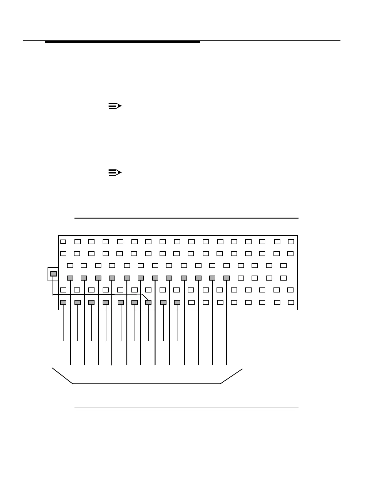
Step 2:
The prepared end of the cable assembly shall be wire wrapped to the
TS1 terminal block in accordance with Figure 3-20a.
NOTE:
There are two black wires to be connected to the TS1 block
(terminals 7 and 24). The black wire to terminal 7 is the
grounded shield from the two shielded pairs of P184. The
black wire to terminal 24 is from P1A.
Step 3:
Add an additional black wire from terminal 7 to the ground lug terminal
on the left mounting screw.
NOTE:
Clock termination resistors and wiring connections to the TS1
block from the CO Clock and the CO Alarms will be made in
subsequent operations. Refer to those sections for details.
Figure 3-20A. ATU/TS1 Wiring Interconnections
2346891
18 19 20 21
22
23 24 25
26
27
28 29
W
BL
O-3BK
W-3BL
W-3S
BK
W-3G
BR
O
S
W-3O
G
BR-3BK
BL-3BK
G-3BK
W-3BR
Refer to Figure 3-20B
57
W-BL
BL
BK
W-O
O