Mahr GmbH, MarSurf M 300 and RD 18
29
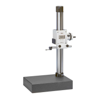
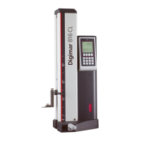
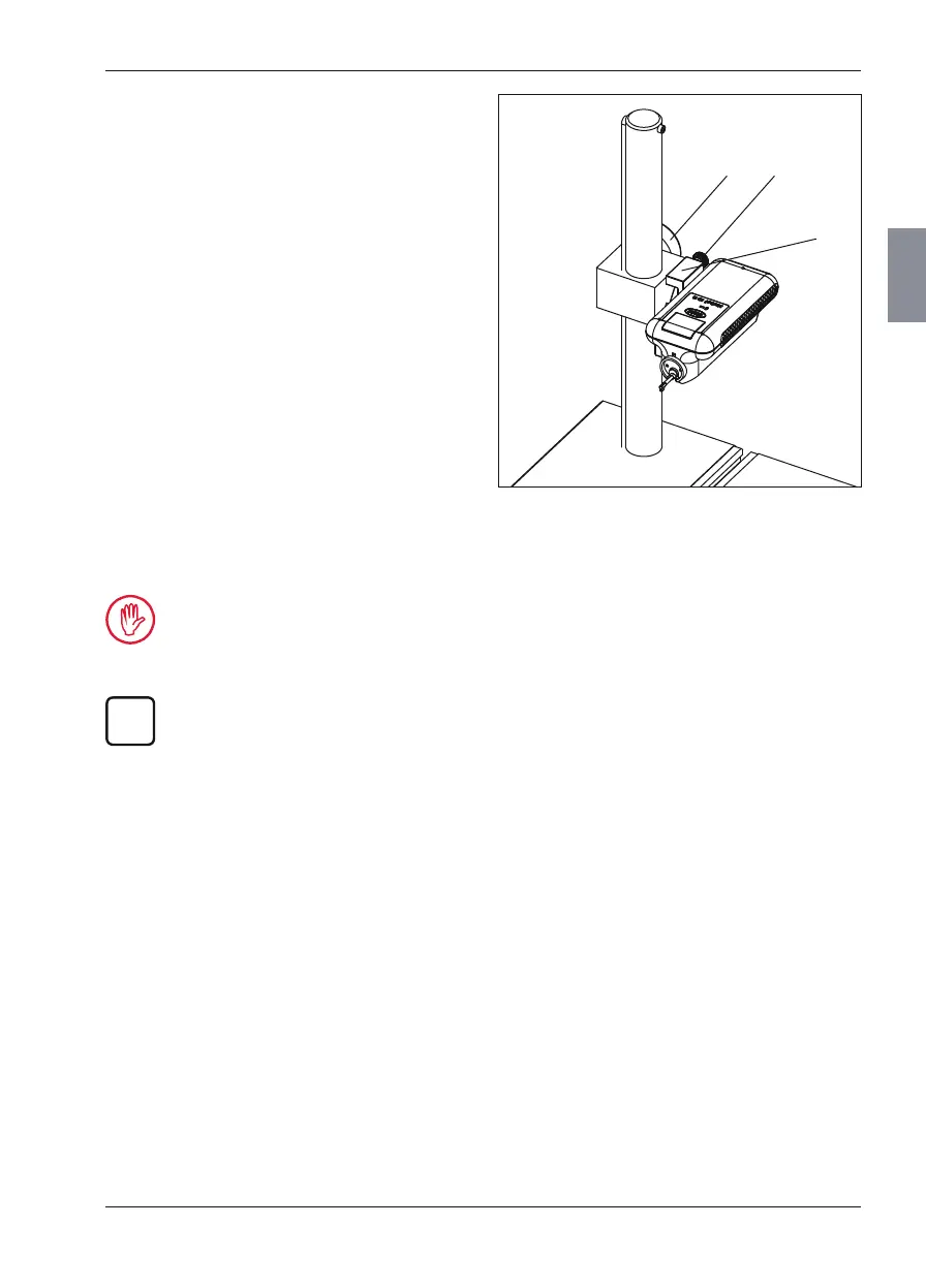
Fig. 10
Stationary meas uring station
with meas uring stand
50 Hand wheel for height adjustment
51 Adjusting screw to correct inclination
52 Holder for MarSurf RD 18 (6910201)
4.3 Setting up the Drive Unit
and Pick-up
4.3.1 Switching the Traverse On/Off
If the testpiece is moved by an external drive,
e. g. the PURV rotation device, the pick-up tra-
verse must be switched off.
The third-party drive system must be set to a
drive speed of 0.5 mm/s.
1. Use the M key to display the "Meas uring
station" view.
2. Activate or deactivate the "Traverse" check
box.
2. Position the MarSurf RD 18 with its bot-
tom side up and then position the holder
(52) such that both of its screws fit into the
threads on the bottom side of the MarSurf
RD 18.
3. Tighten the two screws on the mount.
4. Introduce the mount’s bolt into the orifice
on the cage of the column and clamp it in
place using the two set screws (on the re-
verse of the cage).
5. Use the adjusting screw (51) to align the
testpiece and the drive unit so that they are
parallel with each other. The MarSurf RD 18
can be positioned at an incline of ±15°.
6. Turn the hand wheel for height adjustment
(50) to lower the pick-up to the testpiece.
7. To exchange testpieces, the MarSurf RD 18
can be tipped up and locked in place while
still in the holder.
It is essential that the two screws on the
mount and the two set screws are prop-
erly tightened as otherwise the MarSurf
RD 18 could come off and be damaged!
Both instruments can be supplied with
electricity for stationary operation by
connecting the AC adapter that came
with delivery to the MarSurf M 300 and
creating a cable connection between the
two instruments (see Section 3.3).
 Loading...