MAN B&W 5.10
Page 2 of 2
MAN Diesel
MAN B&W L35MC6
198 63 62-1.0
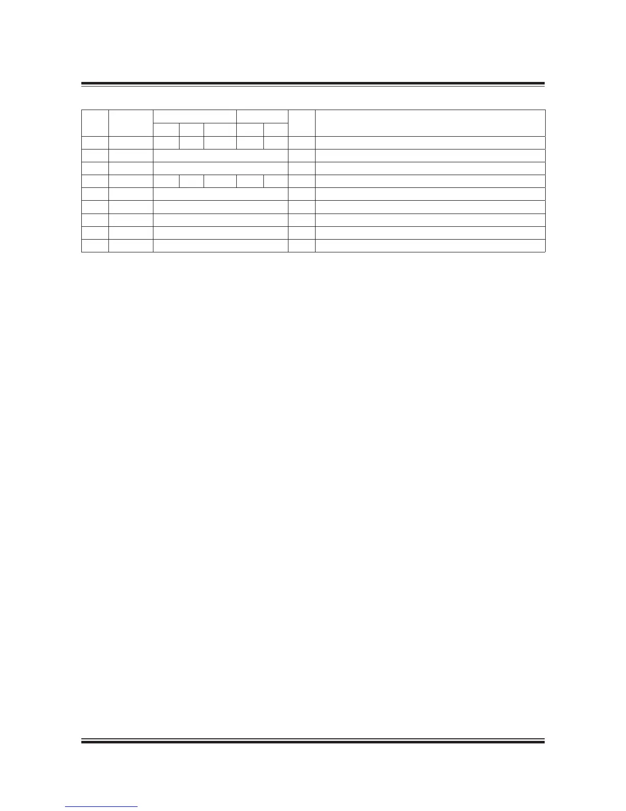
Table 5.10.01: List of counteranges, 6L35MC6 with turbocharger on aft end. Reference is made to section 5.09
Engine Pipe Connections
Refe
rence
Cyl. no.
Flange Bolts
DN * Description
Diam. PCD Thickn. Diam. No.
AR 5-9 30 00 6 M2 4 40 Oil vapour disharge
AS 5-9 Coupling for 6 mm pipe Cooling water drain air cooler
AT 5-9 Coupling for 20 mm pipe Fire extinguishing in scavenge air box
AV 5-9 85 45 20 M6 4 65 Drain from scavenge air chambers to closed drain tank
BB 5-9 Coupling for 0 mm pipe Remote speed setting signal
BB
5-9 Coupling for 0 mm pipe Supply to remote speed setting
BX 5-9 Coupling for 0 mm pipe Steam inlet for heating fuel oil pipes
BF 5-9 Coupling for 0 mm pipe Steam outlet for heating fuel oil pipes
BV 5-9 Coupling for 20 mm pipe Steam inlet for cleaning of drain scavenge air chambers
* DN indicates the nominal diameter of the piping on the engine. For external pipes the diameters should be calculated
according to the uid velocities (see list of capacities) or the recommended pipe sizes in diagrams should be used.
112 13 73-3.1.0

 Loading...


