MAN B&W 1.06
Page 6 of 7
MAN Diesel
MAN B&W S50MC/MC-C-TII, S46MC-C-TII, S42MC-TII,
S35MC-TII, L35MC-TII, S26MC-TII
198 74 728.0
Exhaust Valve
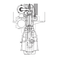
The exhaust valve consists of the valve housing
and the valve spindle. The valve housing is made
of cast iron and is arranged for water cooling. The
housing is provided with a water cooled bottom
piece of steel with a flame-hardened seat of the
W-seat design.
On S50MC and S50MC-C, the exhaust valve spin-
dle is either a DuraSpindle or made of Nimonic.
On engines type 46 and smaller, DuraSpindle is
the basic execution and a spindle made of Ni-
monic an option. The housing is provided with a
spindle guide in any case.
The exhaust valve is tightened to the cylinder cov-
er with studs and nuts. It is opened hydraulically
and closed by means of air pressure. The hydrau-
lic system consists of a piston actuator placed
on the roller guide housing, a highpressure pipe,
and a working cylinder on the exhaust valve. The
piston actuator is activated by a cam on the cam-
shaft.
In operation, the valve spindle slowly rotates, driv-
en by the exhaust gas acting on small vanes fixed
to the spindle.
On engines type 50, 46, 42 and 35, sealing of the
exhaust valve spindle guide is provided by means
of Controlled Oil Level (COL), an oil bath in the
bottom of the air cylinder, above the sealing ring.
This oil bath lubricates the exhaust valve spindle
guide and sealing ring as well.
On S26MC6, sealing of the exhaust valve spindle
guide is provided by means of sealing air.
Cylinder Lubrication
The cylinder lubrication system can be of either
the electronic MAN B&W Alpha cylinder lubrica-
tion system or a mechanical type.
The cylinder lubrication systems are described in
detail in Chapter 9.
Manoeuvring System
The engine is provided with a pneumatic/electric
manoeuvring and fuel oil regulating system. The
system transmits orders from the separate ma-
noeuvring consoles to the engine.
The regulating system makes it possible to start,
stop, reverse the engine and control the engine
speed. The speed control on the manoeuvring
console gives a speedsetting signal to the gover-
nor, dependent on the desired number of revolu-
tions.
At shut-down, the fuel injection is stopped by the
puncture valves in the fuel pumps being activated,
independently of the speed control. At reversing,
the displaceable rollers in the driving mechanism
for the fuel pumps are moved to the ‘Astern’ posi-
tion by an air cylinder controlled by the starting air
distributor.
The engine is provided with an engine side
mounted console and instrument panel.
Reversing
On reversible engines (with Fixed Pitch Propel-
lers mainly), reversing of the engine is performed
by means of an angular displaceable roller in the
driving mechanism for the fuel pump of each
engine cylinder. The reversing mechanism is acti-
vated and controlled by compressed air supplied
to the engine.
The exhaust valve gear is not to be reversed.
Gallery Arrangement
The engine is provided with gallery brackets,
stanchions, railings, platforms, and ladders be-
tween platforms. The brackets are placed at such
a height as to provide the best possible overhaul-
ing and inspection conditions.
The engine is prepared for top bracings on the ex-
haust side, or on the manoeuvring side.

 Loading...