MAN B&W 5.18
Page 7 of 8
MAN Diesel
198 53 221.2MAN B&W S70MC, S70MC-C/ME-C/ME-GI, L70MC-C/ME-C,
S60MC, S60MC-C/ME-C/ME-GI/ME-B, L60MC-C/ME-C,
S50MC, S50MC-C/ME-C/ME-B, S46MC-C/ME-B, S42MC,
S40MC-C/ME-B, S35MC, S35MC-C/ME-B, L35MC, S26MC
2 8 8
BACK UP
CONTROL
ON/OFF
IN
CONTROL
TAKE
CONTROL
PROPELLER
RPM
PROPELLER
PITCH
178 22 418.1
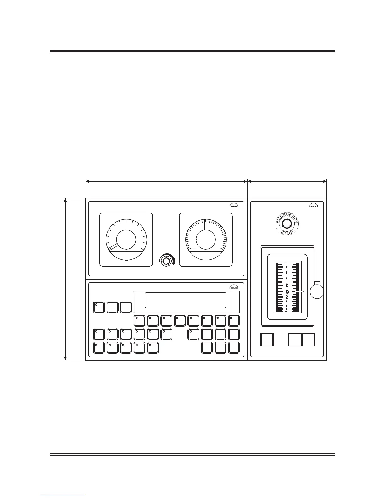
Fig. 5.18.08: Main bridge station standard layout
Propulsion control station on the main bridge
For remote control, a minimum of one control sta-
tion located on the bridge is required.
This control station will incorporate three mod-
ules, as shown in Fig. 5.18.08:
• Propulsion control panel with push buttons
and indicators for machinery control and a dis-
play with information of condition of operation
and status of system parameters.
• Propeller monitoring panel with backup in-
struments for propeller pitch and shaft speed.
• Thrust control panel with control lever for
thrust control, an emergency stop button and
push buttons for transfer of control between
control stations on the bridge.

 Loading...


