MAN B&W 2.04
Page 7 of 10
MAN Diesel
198 69 94-7.1MAN B&W MC/MC-C-TII engines
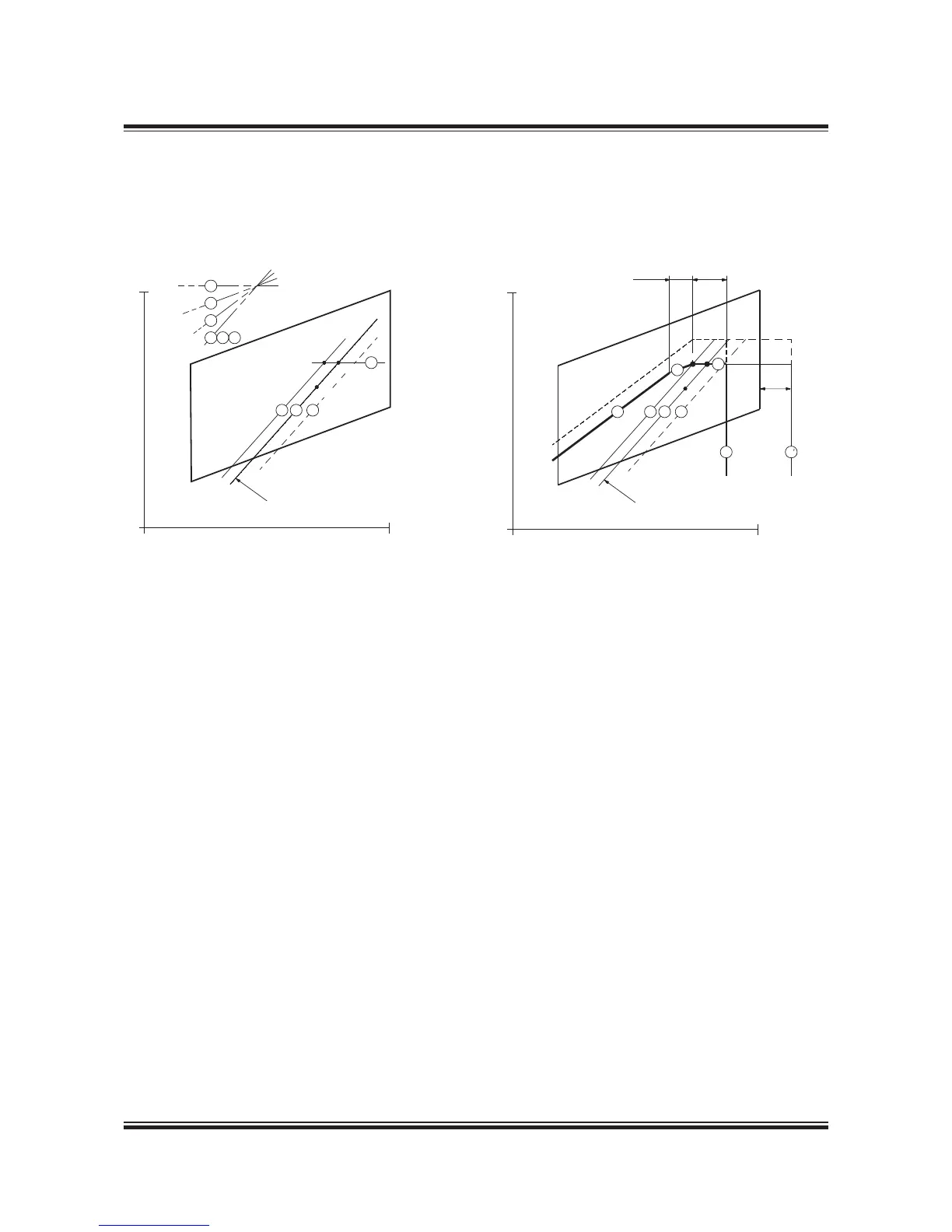
Example 2: Special running conditions.
Engine coupled to a fixed pitch propeller (FPP) and without a shaft generator
M Specified MCR of engine
S Continuous service rating of engine
O Optimising point of engine
A Reference point of load diagram
MP Specified MCR for propulsion
SP Continuous service rating of propulsion
Point A of the load diagram is found:
Line 1 Propeller curve through optimising point (O)
placed to the left of line 2
Line 7 Constant power line through specified MCR (M)
Point A Intersection between line 1 and 7
Layout diagram Load diagram
In this example, the optimising point O has been selected
more to the left than in Example 1, providing an extra en-
gine margin for heavy running operation in heavy weather
conditions. In principle, the light running margin has been
increased for this case.
Fig. 2.04.05: Special running conditions. Engine coupled to a fixed pitch propeller (FPP) and without a shaft generator
178 39 23-1.1
Propulsion and engine
service curve for fouled
hull and heavy weather
Engine speed, % of L
1
100%
Power, % of L
1
100%
7
5
4
1
2
6
1
2 6
M=MP
7
A=O
S=SP

 Loading...


