MAN B&W 2.04
Page 8 of 10
MAN Diesel
198 69 94-7.1MAN B&W MC/MC-C-TII engines
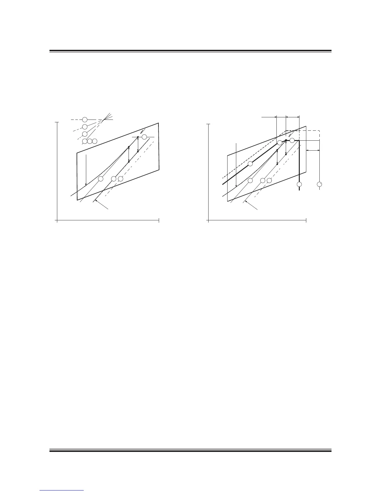
Example 3: Normal running conditions.
Engine coupled to a fixed pitch propeller (FPP) and with a shaft generator
M Specified MCR of engine
S Continuous service rating of engine
O Optimising point of engine
A Reference point of load diagram
MP Specified MCR for propulsion
SP Continuous service rating of propulsion
SG Shaft generator power
Point A of the load diagram is found:
Line 1 Propeller curve through optimising point (O)
Line 7 Constant power line through specified MCR (M)
Point A Intersection between line 1 and 7
Fig. 2.04.06: Normal running conditions. Engine coupled to a fixed pitch propeller (FPP) and with a shaft generator
178 39 25-5.1
In Example 3, a shaft generator (SG) is installed, and therefore
the service power of the engine also has to incorporate the
extra shaft power required for the shaft generator’s electrical
power production.
In the Layout diagram, the engine service curve shown for
heavy running incorporates this extra power.
The optimising point O=A=M will be chosen on the engine
service curve as shown.
Point A is then found in the same way as in Example 1, and
the load diagram can be drawn as shown in the above figure.
Layout diagram Load diagram
Engine speed, % of L
1
100%
Power, % of L
1
100%
7
5
4
1
2
6
1
2
6
Propulsion curve for fouled
hull and heavy weather
Engine
service
curve
7
S
SP
SG
SG
MP

 Loading...


