MAN B&W 2.01
Page 1 of 2
MAN Diesel
198 38 338.4MAN B&W MC/MCC, ME/MEGI/ME-B engines
Engine Layout and Load Diagrams
Introduction
The effective power ‘P’ of a diesel engine is pro-
portional to the mean effective pressure p
e
and
engine speed ‘n’, i.e. when using ‘c’ as a constant:
P = c x p
e
x n
so, for constant mep, the power is proportional to
the speed:
P = c x n
1
(for constant mep)
When running with a Fixed Pitch Propeller (FPP),
the power may be expressed according to the
propeller law as:
P = c x n
3
(propeller law)
Thus, for the above examples, the power P may
be expressed as a power function of the speed ‘n’
to the power of ‘i’, i.e.:
P = c x n
i
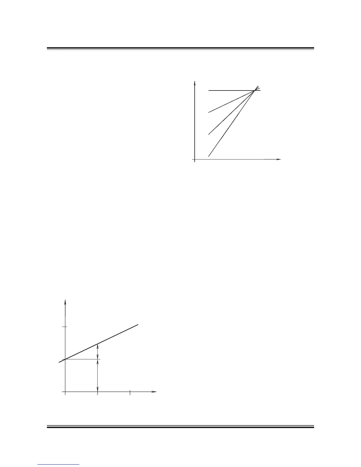
Fig. 2.01.01 shows the relationship for the linear
functions, y = ax + b, using linear scales.
The power functions P = c x n
i
will be linear func-
tions when using logarithmic scales:
log (P) = i x log (n) + log (c)
Fig. 2.01.01: Straight lines in linear scales
Fig. 2.01.02: Power function curves in logarithmic scales
Thus, propeller curves will be parallel to lines hav-
ing the inclination i = 3, and lines with constant
mep will be parallel to lines with the inclination i = 1.
Therefore, in the Layout Diagrams and Load Dia-
grams for diesel engines, logarithmic scales are
used, giving simple diagrams with straight lines.
Propulsion and Engine Running Points
Propeller curve
The relation between power and propeller speed
for a fixed pitch propeller is as mentioned above
described by means of the propeller law, i.e. the
third power curve:
P = c x n
3
, in which:
P = engine power for propulsion
n = propeller speed
c = constant
Propeller design point
Normally, estimates of the necessary propeller
power and speed are based on theoretical cal-
culations for loaded ship, and often experimental
tank tests, both assuming optimum operating
conditions, i.e. a clean hull and good weather. The
combination of speed and power obtained may
be called the ship’s propeller design point (PD),
178 05 403.0
178 05 403.1

 Loading...


