Do you have a question about the Man B&W S80ME-C7 and is the answer not in the manual?
Describes the core concept of the ME engine and its hydraulic activation system.
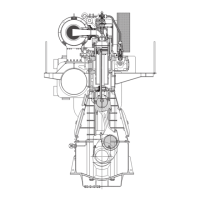
Provides a detailed description of the ME engine's mechanical components and design.
Explains engine layout diagrams and load diagrams using logarithmic scales for clarity.
Details engine layout and load diagrams, defining key points like MCR and matching points.
Describes generator coupling to the main engine via PTO for electrical power production.
Discusses Waste Heat Recovery Systems (WHR) for improving engine efficiency by utilizing exhaust gas energy.
Explains the PTG system, its performance, and arrangement.
Describes the STG system, utilizing exhaust gas energy to produce steam for turbines.
Discusses combined PTG and STG systems for maximum exhaust gas energy utilization.
Details space requirements and overhaul heights for engines, including crane lifting capacities.
Explains the purpose and types of engine top bracing to mitigate vibrations.
Lists components for the Engine Control System installed in the engine control room.
Details the Main Operating Panel (MOP) and track ball for engine control.
Explains the scope, design, and purpose of the shaftline earthing device to prevent spark erosion.
Describes necessary auxiliary machinery capacities and exhaust gas data for nominally rated engines.
Explains how to calculate cooler capacities for derated engines using heat dissipation values.
Provides an example calculation for pump and cooler capacities of a derated engine.
Describes factors influencing exhaust gas data and calculation methods.
Demonstrates the calculation of expected exhaust gas amount and temperature for a derated engine.
Describes the pressurized fuel oil system for both diesel oil and heavy fuel oil.
Explains Water In Fuel emulsion (WIF) for NOx reduction and its impact on engine systems.
Details the lubricating and cooling oil system, including modifications for ME engines.
Explains the Hydraulic Power Supply (HPS) unit, its purpose, and available versions.
Details components of the lubricating oil system, including pumps, coolers, and temperature control.
Explains the back-flushing of hydraulic control oil and suggestions for managing contaminated oil.
Details the separate system for hydraulic control units, including components and data.
Presents detailed data for the hydraulic control oil system of the S80ME-C engine.
Discusses the importance of cylinder lubrication costs and optimization.
Explains the Alpha cylinder lubrication system with electronic timing and dosage.
Describes the Alpha ACC system for optimizing cylinder lubrication based on fuel quality and load.
Details the piston rod stuffing box drain oil system, emphasizing separation for heavy fuel engines.
Explains the central cooling water system, its characteristics, and temperature control.
Details components of the central cooling water system, including pumps, coolers, and valves.
Discusses the advantages and disadvantages of seawater cooling systems compared to central cooling.
Explains the seawater cooling system, its components, and inter-related positioning for optimal performance.
Details components of the seawater cooling system, including pumps, coolers, and thermostatic valves.
Describes the jacket cooling water system and its function in cooling engine parts.
Details components for the jacket cooling water system, including pumps, preheaters, and tanks.
Outlines temperature restrictions for starting the engine to prevent corrosive attacks.
Describes the starting and control air systems, including supply pressures and components.
Details components of the starting air system, such as compressors, receivers, and reduction stations.
Explains the scavenge air system, its integration with turbochargers, and cooling.
Details the engine's auxiliary blowers, their control, and emergency running functions.
Details fire extinguishing systems for the scavenge air space using steam, water mist, or CO2.
Explains how exhaust gas is led from cylinders to the turbocharger, including compensators and insulation.
Covers the main engine exhaust gas system, including back-pressure limits and design parameters.
Explains how to calculate exhaust gas back-pressure based on system components and velocity.
Illustrates vectors of thermal expansion and lists permissible forces and moments on turbocharger flanges.
Describes the ME engine control system, its interfaces, and redundancy features.
Details the MOP as the operator's interface for engine control and status monitoring.
Explains the function of ECUs in controlling engine parameters and auxiliary functions.
Describes the CCU's role in controlling fuel injection and exhaust valve activation per cylinder.
Describes the LOP as an alternative control station for engine operation.
Explains the HPS unit's purpose in delivering high-pressure hydraulic oil to HCUs.
Shows a diagram of the engine control system layout across different locations.
Illustrates the mechanical-hydraulic system with the HPS unit mounted on the engine.
Describes how the Engine Control System interfaces with ship control systems like alarms and telegraph.
Describes the engine safety system's role in preventing overloading and ensuring safe operation.
Discusses vibration characteristics of diesel engines and categories of vibration sources.
Explains external unbalanced moments arising from engine masses and their classification.
Defines guide force moments caused by transverse forces on crossheads.
Recommends top bracing to mitigate engine vibrations and resonance issues.
Addresses 2nd order moments, precautions for 6-cylinder engines, and resonance issues.
Describes electrically driven moment compensators as an alternative to mitigate vibrations.
Introduces Power Related Unbalance (PRU) as a guidance for assessing hull vibration risks.
Defines H-type and X-type guide force moments and their calculation.
Details the calculation of X-type guide force moments, considering engine type and cylinder count.
Discusses axial vibrations caused by crank throw deflection and the role of axial dampers.
Explains torsional vibrations in the shaft system and the need for dampers or QPT.
Discusses critical running conditions related to varying torque and propeller thrust.
Explains overcritical running conditions and their characteristics.
Describes the Engine Control System (ECS) supported by PMI and CoCoS-EDS for engine monitoring.
Lists the basic components of the ME engine instrumentation.
Explains the PMI system for measuring cylinder pressure and engine parameters.
Introduces CoCoS systems as software products for diagnostics and performance evaluation.
Details CoCoS-EDS features like online data logging, monitoring, and reporting.
Explains the alarm, slow down, and shut down systems, including sensor requirements.
Lists alarm functions for UMS, correlating sensors to points of location and class requirements.
Lists slow down functions for UMS, correlating sensors to points of location.
Explains Bearing Wear Monitoring (BWM) systems for predicting bearing wear and preventing damage.
Details the function and types of oil mist detectors for crankcase atmosphere monitoring.
Describes the BWM system for monitoring bearing temperatures and wear.
Explains the Water In Oil (WIO) monitoring system to detect and prevent water contamination.
Details the BTM system for monitoring bearing temperatures.
Provides a comprehensive guide to identifying instruments and sensors using codes and location numbers.
Divides dispatch patterns into classes (A and B) based on transportation distance and storage duration.
Explains the procedure for shop trials and delivery tests before engine works departure.
Discusses the importance of spare parts and MAN Diesel's recommendations for stocking them.
Lists unrestricted spare parts required for engines based on class specifications.
Lists standard tools necessary for engine overhauling.
Explains MAN Diesel's support services for shipping and shipbuilding industries.
Describes Engine Selection Guides as tools for initial project stage assistance.
Introduces the Computerised Engine Application System for specific project calculations.
Explains the Extent of Delivery (EoD) sheets as a basis for specifying scope and options.
| Bore | 800 mm |
|---|---|
| Stroke | 3450 mm |
| Cylinder Arrangement | Inline |
| Fuel Type | Heavy Fuel Oil (HFO) |
| Emission Compliance | IMO Tier II (Tier III with SCR) |
| Length | Varies by cylinder count |
| Engine Type | 2-stroke, low-speed diesel engine |


 Loading...