MAN B&W 2.04
Page 8 of
MAN Diesel
MAN B&W ME/ME-C/ME-GI engines
198 38 97-3.6
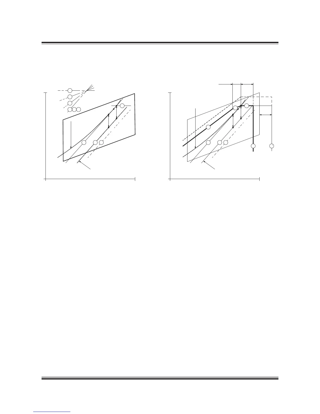
Example 3:
Normal running conditions. Engine coupled to xed pitch propeller (FPP) and with shaft generator
M Specied MCR of engine
S Continuous service rating of engine
O Matching point of engine
A Reference point of load diagram
MP Specied MCR for propulsion
SP Continuous service rating of propulsion
SG Shaft generator power
Point A of load diagram is found:
Line Propeller curve through matching point (O)
Line 7 Constant power line through specied MCR (M)
Point A Intersection between line and 7
Example 3, Layout diagram for normal running conditions,
engine with FPP and with shaft generator
Example 3, Load diagram for normal running conditions,
engine with FPP and with shaft generator
178 55 84-9.0
In example 3 a shaft generator (SG) is installed,
and therefore the service power of the engine also
has to incorporate the extra shaft power required
for the shaft generator’s electrical power produc-
tion.
In the gure, the engine service curve shown for
heavy running incorporates this extra power.
The matching point O will normally be chosen on
the propeller curve (~ the engine service curve)
through point M.
Point A is then found in the same way as in ex-
ample and the load diagram can be drawn as
shown in the gure.

 Loading...


