K90ME, S80ME-C, S70ME-C/ME-GI, S60ME-C/ME-GI, S50ME-C 198 44 22-2.1
MAN B&W Diesel A/S 6.04
Page 9 of 12
∆m
M%
: change of specific exhaust gas amount,
in % of specific gas amount at nominal
MCR (L
1
), see Fig. 6.04.07.
∆T
M
: change in exhaust gas temperature after
turbocharger relative to the L1 value, in °C,
see Fig. 6.04.08. (P
O
= P
M
)
∆T
O
: extra change in exhaust gas temperature
when matching point O lower than 100% M:
P
O%
= (P
O
/P
M
) x 100%.
∆T
O
= - 0.3 x (100 - P
O%
) [6]
b) Correction for actual ambient conditions and
back-pressure
For ambient conditions other than ISO 3046/1
1995 (E), and back-pressure other than 300 mm
WC at specified MCR point (M), the correction
factors stated in the table in Fig. 6.04.09 may be
used as a guide, and the corresponding relative
change in the exhaust gas data may be found
from equations [7] and [8], shown in Fig. 6.04.10.
Parameter Change Change of Change of
exhaust gas exhaust gas
temperature amount
Blower inlet temperature + 10° C + 16.0° C - 4.1 %
Blower inlet pressure (barometric pressure) + 10 mbar - 0.1° C + 0.3 %
Charge air coolant temperature + 10° C + 1.0° C + 1.9 %
(seawater temperature)
Exhaust gas back pressure at the specified MCR point + 100 mm WC + 5.0° C -1.1 %
Fig. 6.04.09: Correction of exhaust gas data for ambient conditions and exhaust gas back pressure
Specified MCR
power, % of L
1
P
M%
110%
100%
90%
80%
70%
50%
40%
70% 75% 80% 85% 90% 95%
M%
Specified MCR engine speed, % of L
3
4
2
1
60%
105%100% 110%
n
M
0%
-2%
-4%
-6%
T
m
-22 C
-20 C
-18 C
-16 C
-14 C
-12 C
-10 C
-8 C
∆m
M%
= 14 x ln (P
M
/P
L
1
) – 24 x ln (n
M
/n
L
1
)
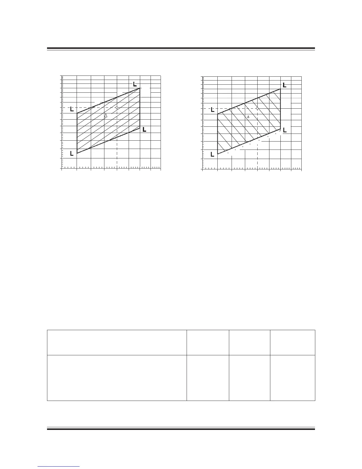
Fig. 6.04.07: Change of specific exhaust gas amount,
∆
m
M%
in % of L
1
value and independent of P
O
∆T
M
= 15 x ln (P
M
/P
L
1
) + 45 x ln (n
M
/n
L
1
)
Fig. 6.04.08: Change of exhaust gas temperature,
∆
T
M
in
point M, in °C after turbocharger relative to L
1
value and
valid for P
O
= P
M
178 51 09-5.0 178 51 12-9.0

 Loading...


