MAN B&W 15.04
Page of 2
MAN Diesel
198 40 758.6MAN B&W MC/MCC, ME/MEC/MEGI/ME-B engines
Components of the Exhaust Gas System
Exhaust gas boiler
Engine plants are usually designed for utilisation of
the heat energy of the exhaust gas for steam pro-
duction or for heating the thermal oil system. The
exhaust gas passes an exhaust gas boiler which is
usually placed near the engine top or in the funnel.
It should be noted that the exhaust gas tempera-
ture and ow rate are inuenced by the ambient
conditions, for which reason this should be con-
sidered when the exhaust gas boiler is planned. At
specied MCR, the maximum recommended pres-
sure loss across the exhaust gas boiler is normally
50 mm WC.
This pressure loss depends on the pressure losses
in the rest of the system as mentioned above.
Therefore, if an exhaust gas silencer/spark ar-
rester is not installed, the acceptable pressure loss
across the boiler may be somewhat higher than the
max. of 50 mm WC, whereas, if an exhaust gas
silencer/spark arrester is installed, it may be neces-
sary to reduce the maximum pressure loss.
The above mentioned pressure loss across the
exhaust gas boiler must include the pressure
losses from the inlet and outlet transition pieces.
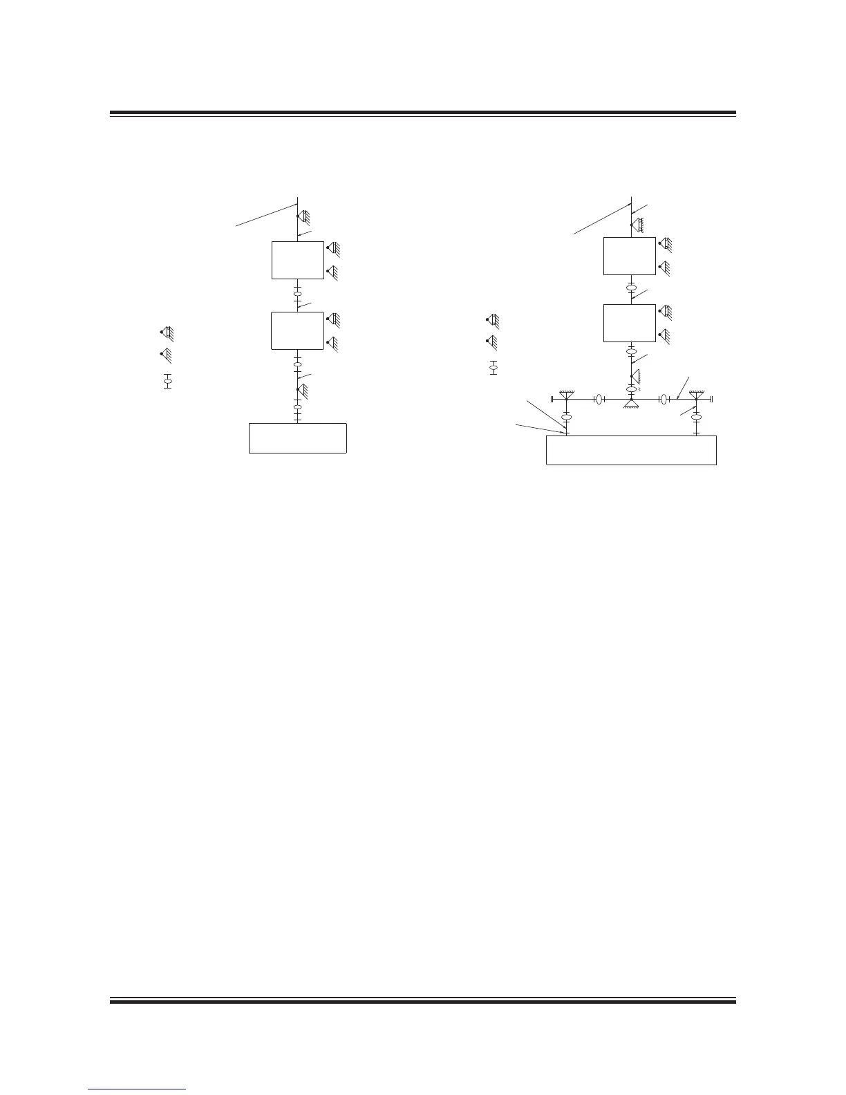
Fig. 15.04.01a: Exhaust gas system, one turbocharger
178 42 783.2
Exhaust gas compensator after turbocharger
When dimensioning the compensator (option:
4 60 60) for the expansion joint on the turbochar-
ger gas outlet transition piece (option: 4 60 60)
the exhaust gas piece and components, are to be
so arranged that the thermal expansions are ab-
sorbed by expansion joints. The heat expansion of
the pipes and the components is to be calculated
based on a temperature increase from 20 °C to
250 °C. The max. expected vertical, transversal
and longitudinal heat expansion of the engine
measured at the top of the exhaust gas transition
piece of the turbocharger outlet are indicated in
Fig. 5.06.0 and Table 5.06.02 as DA, DB and DC.
The movements stated are related to the engine
seating, for DC, however, to the engine centre. The
gures indicate the axial and the lateral movements
related to the orientation of the expansion joints.
The expansion joints are to be chosen with an elas-
ticity that limits the forces and the moments of the
exhaust gas outlet ange of the turbocharger as
stated for each of the turbocharger makers in Table
5.06.04. The orientation of the maximum permis-
sible forces and moments on the gas outlet ange
of the turbocharger is shown in Fig. 5.06.03.

 Loading...


