MAN B&W 6.04
Page of 12
MAN Diesel
MAN B&W ME/MEC/MEGI engines 198 43 012.2
Freshwater Generator
If a freshwater generator is installed and is utilis-
ing the heat in the jacket water cooling system,
it should be noted that the actual available heat
in the jacket cooling water system is lower than
indicated by the heat dissipation gures valid for
nominal MCR (L
1
) given in the List of Capacities.
This is because the latter gures are used for
dimensioning the jacket water cooler and hence
incorporate a safety margin which can be needed
when the engine is operating under conditions
such as, e.g. overload. Normally, this margin is
10% at nominal MCR.
Calculation Method
For a derated diesel engine, i.e. an engine having
a specied MCR (M) and/or a matching point (O)
different from L
1
, the relative jacket water heat dis-
sipation for point M and O may be found, as previ-
ously described, by means of Fig. 6.04.02.
At part load operation, lower than matching pow-
er, the actual jacket water heat dissipation will be
reduced according to the curves for xed pitch
propeller (FPP) or for constant speed, controllable
pitch propeller (CPP), respectively, in Fig. 6.04.04.
With reference to the above, the heat actually
available for a derated diesel engine may then be
found as follows:
1. Engine power between matching and speci-
ed power.
For powers between specied MCR (M) and
matching power (O), the diagram Fig. 6.04.02
is to be used, i.e. giving the percentage cor-
rection factor ‘Q
jw%
’ and hence for matching
power P
O
:
Q
jw,O
= Q
jw,L1
x
Q
jw%
___
100
x 0.9 (0.88) [1]
2. Engine power lower than matching power.
For powers lower than the matching power,
the value Q
jw,O
found for point O by means of
the above equation [1] is to be multiplied by
the correction factor k
p
found in Fig. 6.04.04
and hence
Q
jw
= Q
jw,O
x k
p
1%/0% [2]
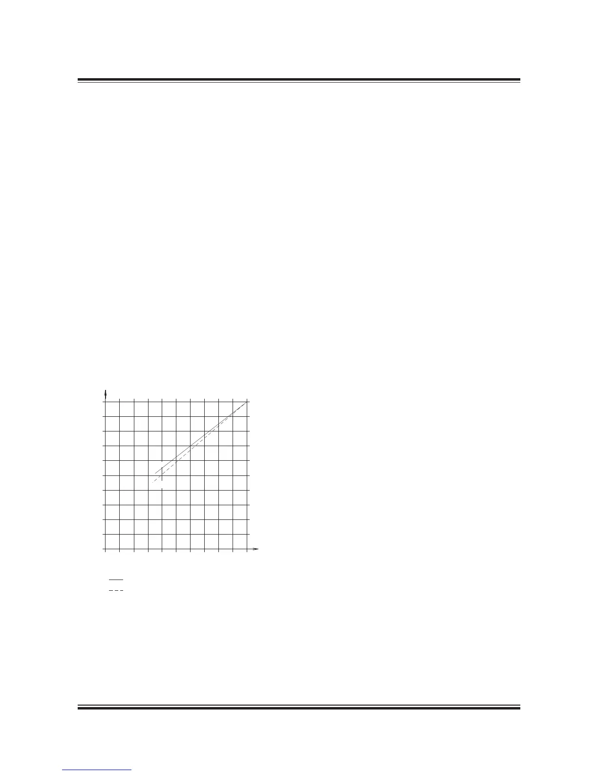
Part load correction factor for jacket
cooling water heat dissipation
Engine load, % of matching power (O)
FPP : Fixed pitch propeller
CPP : Controllable pitch propeller, constant speed
k
p
1.0
0.9
0.8
0.7
0.6
0.
0.4
0.3
0.2
0.1
0
0 10 20 30 40 0 60 70 80 90
100%
FPP
CPP
178 06 643.2
Fig. 6.04.04: Correction factor ‘kp’ for jacket cooling
water heat dissipation at part load, relative to heat dis-
sipation at matching power
FPP : k
p
= 0.742 x
P
S
__
P
O
+ 0.28
CPP : k
p
= 0.822 x
P
S
__
P
O
+ 0.178
where
Q
jw
= jacket water heat dissipation
Q
jw,L1
= jacket water heat dissipation at nominal
MCR (L
1
)
Q
jw%
= percentage correction factor from
Fig. 6.04.02
Q
jw,O
= jacket water heat dissipation at matching
power (O), found by means of equation [1]
k
p
= part load correction factor from Fig. 6.04.04
0.9 = factor for safety margin of cooler, tropical
ambient conditions
The heat dissipation is assumed to be more or less
independent of the ambient temperature conditions,
yet the safety margin/ambient condition factor of
about 0.88 instead of 0.90 will be more accurate for
ambient conditions corresponding to ISO tempera-
tures or lower. The heat dissipation tolerance from
1% to 0% stated above is based on experience.

 Loading...


