K90ME, S80ME-C, S70ME-C/ME-GI, S60ME-C/ME-GI, S50ME-C 198 42 98-7.2
MAN B&W Diesel A/S 6.04
Page 1 of 12
Auxiliary Machinery Capacities
The dimensioning of heat exchangers (coolers) and
pumps for derated engines can be calculated on
the basis of the heat dissipation values found by
using the following description and diagrams. Those
for the nominal MCR (L
1
), may also be used if
wanted.
The nomenclature of the basic engine ratings and
coolers, etc. used in this section is shown in Fig.
6.01.01 and 6.01.02.
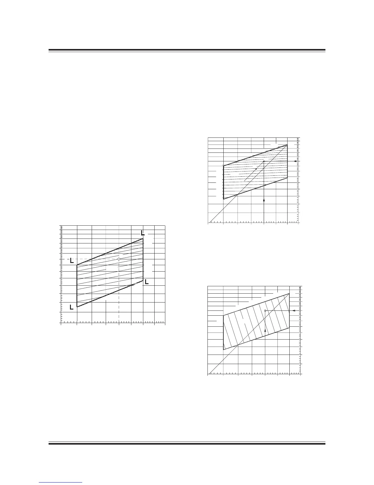
Cooler heat dissipations
For the specified MCR (M) the following three dia-
grams in Figs. 6.04.01, 6.04.02 and 6.04.03 show re-
duction factors for the corresponding heat dissipa-
tions for the coolers, relative to the values stated in
the ‘List of Capacities’ valid for nominal MCR (L
1
).
3
4
2
1
M
Q
air%
40%
45%
100%
90%
80%
70%
60%
55%
50%
The percentage power (P
M%
) and speed (n
M%
) of L
1
ie: P
M%
= P
M
/P
L
1
x 100%
n
M%
= n
M
/n
L
1
x 100%
for specified MCR (M) of the derated engine is used
as input in the above-mentioned diagrams, giving
the % heat dissipation figures relative to those in
the ‘List of Capacities’,
Q
air%
= 100 x (P
M
/P
L1
)
1.68
x (n
M
/n
L1
)
– 0.83
x k
O
k
O
= 1 + 0.27 x (1 – P
O
/P
M
)
178 24 57-6.0
Fig. 6.04.01: Scavenge air cooler, heat dissipation Q
air%
in
point M, in % of the L
1
value Q
air, L
1
and valid for P
O
= P
M
.
If matching point O lower than M, an extra correction k
O
is used
P
M%
110%
100%
90%
80%
70%
60%
50%
40%
Specified MCR
power, % af L
1
M
Q
lub%
78
76
80%
82%
84%
86%
88%
90%
92%
94%
96%
98%
L
1
Q
jw%
= e
(– 0.0811 x ln (n
M%
)
+ 0.8072 x ln (P
M%
) + 1.2614)
Fig. 6.04.02: Jacket water cooler, heat dissipation Q
jw%
in
point M, in% of the L
1
value Q
jw, L
1
178 50 16-0.0
Q
lub%
= 67.3009 x ln (n
M%
) + 7.6304 x ln (P
M%
)
- 245.0714
Fig. 6.04.03: Lubricating oil cooler, heat dissipation Q
lub%
in poiunt M, in % of the L
1
value Q
lub, L
1
178 08 07-7.1

 Loading...


