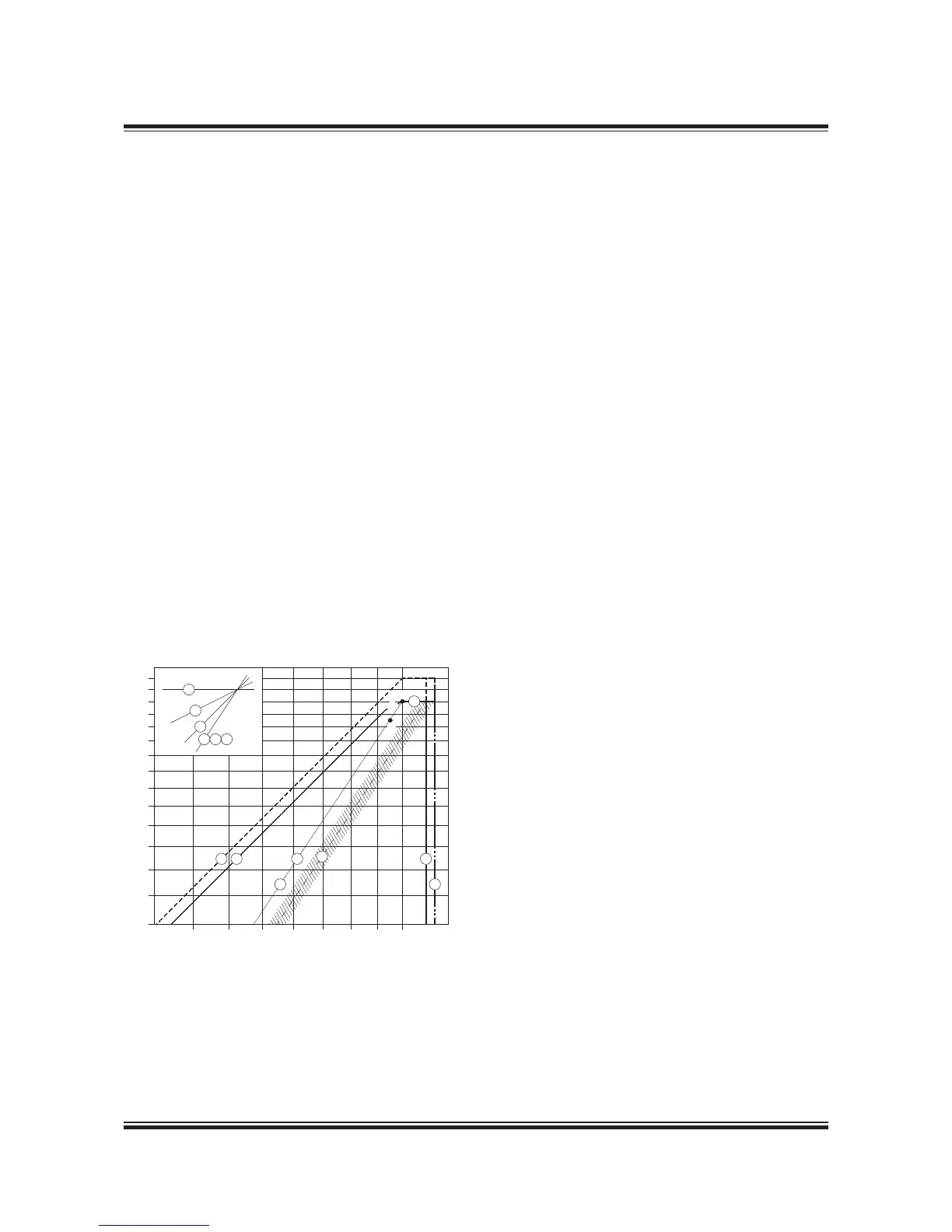
A 00% reference point
M Specied MCR
O Matching point
Fig. 2.04.02: Standard engine load diagram
Regarding ‘i’ in the power function P = c x n
i
, see page 2.0
178 05 427.3
Engine Load Diagram
Denitions
The engine’s load diagram denes the power and
speed limits for continuous as well as overload
operation of an installed engine having a specied
MCR point M that conrms the ship’s specication.
Point A is a 00% speed and power reference
point of the load diagram, and is dened as the
point on the propeller curve (line ), the layout
curve of the engine through the matching point
O, having the specied MCR power. Normally,
point M is equal to point A, but in special cases,
for example if a shaft generator is installed, point
M may be placed to the right of point A on line 7.
However, MAN Diesel may always consider point
A as the engine’s MCR for shop test.
In most cases, the points M and A are identical.
The service points of the installed engine incorpo-
rate the engine power required for ship propulsion
and shaft generator, if installed.
Operating curves and limits for continuous
operation
The continuous service range is limited by four
lines:
4, 5, 7 and 3 (9), see Fig. 2.04.02. The propeller
curves, line , 2 and 6 in the load diagram are also
described below.
Line 1:
Propeller curve through specied MCR (M), en-
gine layout curve (i = 3).
Line 2:
Propeller curve, fouled hull and heavy weather
– heavy running (i = 3).
Line 3 and line 9:
Line 3 represents the maximum acceptable speed
for continuous operation, i.e. 05% of A.
During trial conditions the maximum speed may
be extended to 07% of A, see line 9.
The above limits may in general be extended to
05% and during trial conditions to 07% of the
nominal L
speed of the engine, provided the tor-
sional vibration conditions permit.
The overspeed setpoint is 09% of the speed
in A, however, it may be moved to 09% of the
nominal speed in L
, provided that torsional vibra-
tion conditions permit.
Running at low load above 00% of the nominal L
speed of the engine is, however, to be avoided for
extended periods. Only plants with controllable
pitch propellers can reach this light running area.
Line 4:
Represents the limit at which an ample air supply
is available for combustion and imposes a limita-
tion on the maximum combination of torque and
speed (i = 2).
Line 5:
Represents the maximum mean effective pressure
level (mep), which can be accepted for continuous
operation (i = ).

 Loading...


