178 06 816.3
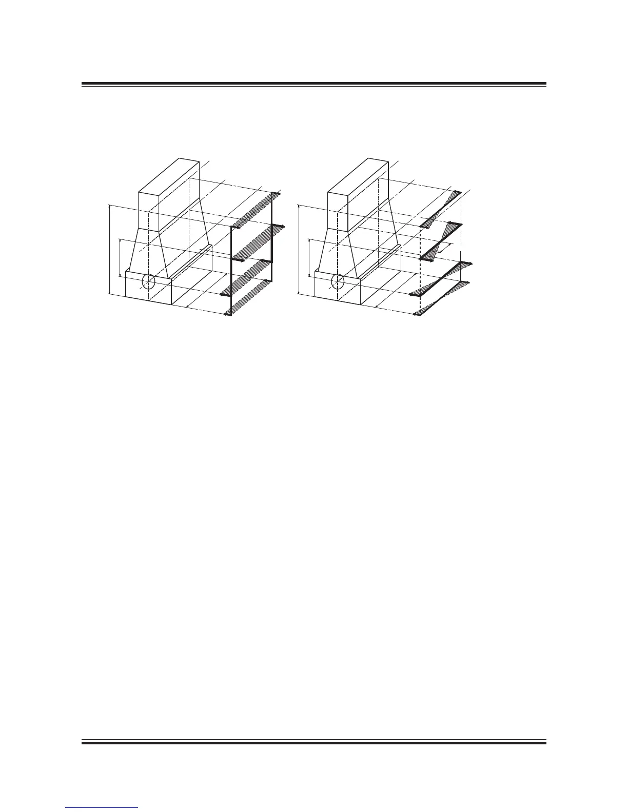
Fig. 17.05.01: Htype and Xtype guide force moments
The socalled guide force moments are caused
by the transverse reaction forces acting on the
crossheads due to the connecting rod/cranskahft
mechanism. These moments may excite engine
vibrations, moving the engine top athwartships
and causing a rocking (excited by Hmoment) or
twisting (excited by Xmoment) movement of the
engine as illustrated in the above gure.
The guide force moments corresponding to the
MCR rating (L
) are stated in Table 7.07.0.
Top bracing
The guide force moments are harmless except
when resonance vibrations occur in the engine/
double bottom system.
As this system is very difcult to calculate with the
necessary accuracy MAN Diesel strongly recom-
mend, as standard, that top bracing is installed
between the engine’s upper platform brackets
and the casing side.
The vibration level on the engine when installed in
the vessel must comply with MAN Diesel vibration
units as stated in Fig. 7.05.02.
We recommend using the hydraulic top bracing
which allow adjustment to the loading conditions
of the ship. Mechanical top bracings with stiff
connections are available on request.
With both types of top bracing abovementioned
natural frequency will increase to a level where res-
onance will occur above the normal engine speed.
Details of the top bracings are shown in Chapter 05.
Denition of Guide Force Moments
Over the years it has been discussed how to de-
ne the guide force moments. Especially now that
complete FEMmodels are made to predict hull/
engine interaction, the propeller denition of these
moments has become increasingly important.
Htype Guide Force Moment (M
H
)
Each cylinder unit produces a force couple con-
sisting of:
. A force at crankshaft level.
2. Another force at crosshead guide level. The
position of the force changes over one revo-
lution as the guide shoe reciprocates on the
guide.

 Loading...


