MAN B&W 7.05
Page of
MAN Diesel
MAN B&W S90MEC, S80MEC, K80MEC 198 41 179.0
Fuel oil lter
The lter can be of the manually cleaned duplex
type or an automatic lter with a manually cleaned
bypass lter.
If a double lter (duplex) is installed, it should
have sufcient capacity to allow the specied full
amount of oil to ow through each side of the lter
at a given working temperature with a max. 0.
bar pressure drop across the lter (clean lter).
If a lter with backushing arrangement is
installed, the following should be noted. The re-
quired oil ow specied in the ‘List of capacities’,
i.e. the delivery rate of the fuel oil supply pump
and the fuel oil circulating pump, should be in-
creased by the amount of oil used for the back-
ushing, so that the
fuel oil pressure at the inlet to the main engine can
be maintained during cleaning.
In those cases where an automatically cleaned
lter is installed, it should be noted that in order
to activate the cleaning process, certain makers
of lters require a greater oil pressure at the inlet
to the lter than the pump pressure specied.
Therefore, the pump capacity should be adequate
for this purpose, too.
The fuel oil lter should be based on heavy fuel oil
of: 10 cSt at 80 °C = 700 cSt at 50 °C = 7000 sec
Redwood I/100 °F.
Fuel oil ow .........................see ‘List of capacities’
Working pressure .......................................... 10 bar
Test pressure ...................... according to class rule
Absolute neness .......................................... 50 µm
Working temperature .................. maximum 150 °C
Oil viscosity at working temperature ............15 cSt
Pressure drop at clean lter ........maximum 0. bar
Filter to be cleaned at a pressure
drop at ........................................maximum 0.5 bar
Note:
Absolute neness corresponds to a nominal ne-
ness of approximately 30 µm at a retaining rate of
90%.
The lter housing shall be tted with a steam jack-
et for heat tracing.
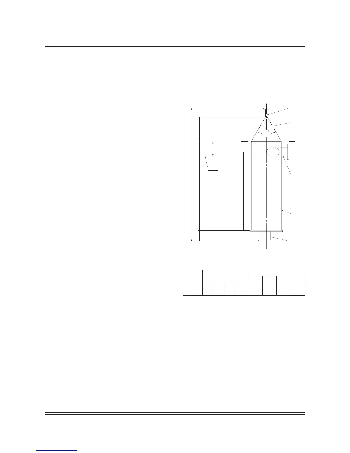
Fuel oil venting box
The design is shown on ‘Fuel oil venting box’, see
Fig. 7.05.02
Flow m
/h Dimensions in mm
Q (max.)* D1 D2 D H1 H2 H H4 H5
11.5 400 90 15 150 1,200 .5 1,800 1,100
19.5 400 125 15 150 1,200 .5 1,800 1,100
Fig. 07.05.02: Fuel oil venting box
Flushing of the fuel oil system
Before starting the engine for the rst time, the
system on board has to be ushed in accordance
with MAN B&W’s recommendations ‘Flushing of
Fuel Oil System’ which is available on request.
* The actual maximum ow of the fuel oil circulation pump
178 38 393.2

 Loading...


