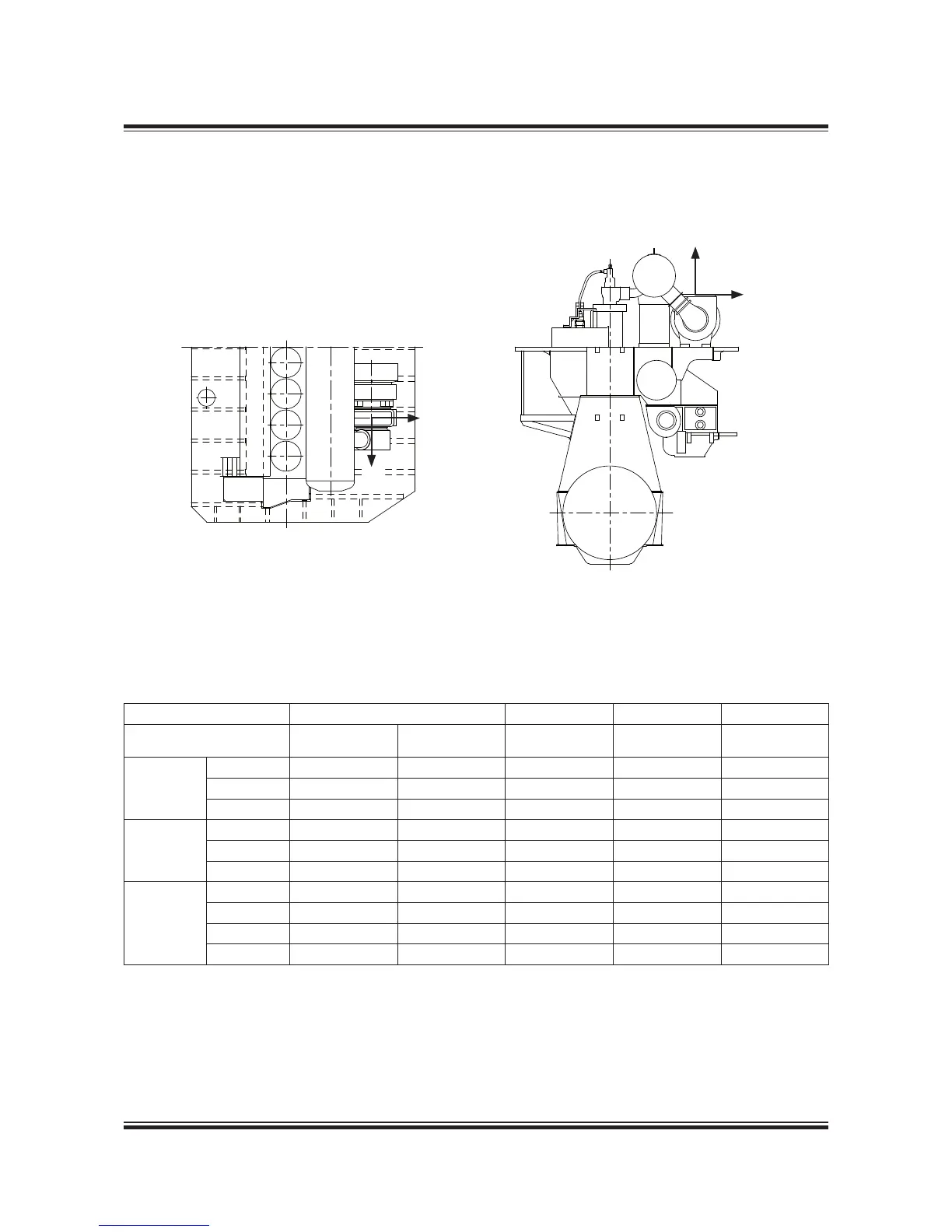
Fig. 15.06.01: Vectors of thermal expansion at the turbocharger exhaust gas outlet ange
078 87 11-1.0.0b
Table 15.06.02: Max. expected movements of the exhaust gas ange resulting from thermal expansion
No. of cylinders 6-8 6 7 8
Turbocharger DA DB DC DC DC
Make Type mm mm mm mm mm
MAN Diesel
TCA77 9.8 .5 2. 2.4 2.7
TCA88 0.3 .6 2. 2.4 2.7
NA70 9.9 .5 2. 2.4 2.7
ABB
TPL80 8.5 .5 2. 2.4 2.7
TPL85 9.5 .5 2. 2.4 2.7
TPL9 0.5 .8 2.
2.4 2.7
MHI
MET66 8.4 .5 2. 2.4 2.7
MET7
8.8 .5 2. 2.4 2.7
MET83 9.5 .5 2. 2.4 2.7
MET90 0.0 .7 2. 2.4 2.7
DA: Max. movement of the turbocharger ange in the vertical direction
DB: Max. movement of the turbocharger ange in the transversal direction
DC: Max. movement of the turbocharger ange in the longitudinal direction

 Loading...


