Table 15.06.04: The max. permissible forces and moments on the turbocharger’s gas outlet anges
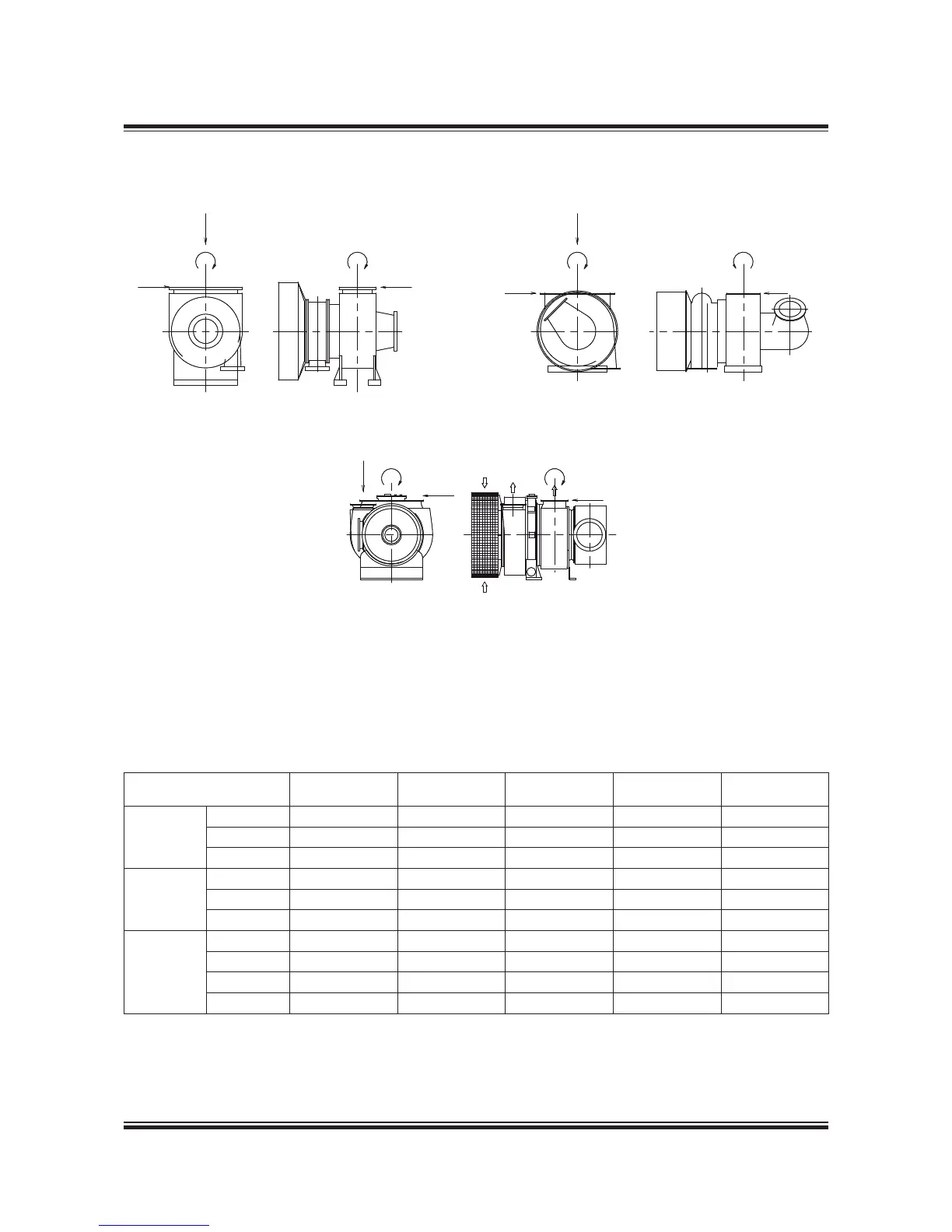
Fig. 15.06.03: Forces and moments on the turbochargers’ exhaust gas outlet ange
Table 5.06.04 indicates the maximum permis
sible forces (F, F2 and F3) and moments (M and
M3), on the exhaust gas outlet ange of the turbo
charger(s). Reference is made to Fig. 5.06.03.
Turbocharger M1 M3 F1 F2 F3
Make Type Nm Nm N N N
MAN Diesel
TCA77 4,00 8,200 0,900 0,900 5,400
TCA88 4,500 9,00 2,000 2,000 5,900
NA70 5,300 3,500 8,800 8,800 3,500
ABB
TPL80 ,000 ,000 5,000 3,000 3,000
TPL85 6,000 6,000 9,000 5,000 5,000
TPL9
20,000 20,000 22,000 7,500 7,500
MHI
MET66 6,800 3,400 9,300 3,200 3,000
MET7
7,000 3,500 9,600 3,300 3,00
MET83 9,800 4,900 ,700 4,00 3,700
MET90 ,00 5,500 2,700 4,400 4,000

 Loading...


