MAN B&W 15.01
Page of
MAN Diesel
MAN B&W K108MEC6, K98MC/ME6/7, K98MC-C/MEC6/7,
S90MC-C/MEC7/8, K90MC-C/ME-C6, K90ME/MEC9, S80MC6,
S80MC-C7/8, S80MEC7/8/9, K80MC-C6, K80MEC6/9, S70MC6,
S70MC-C/MEC/MEGI7/8, L70MC-C/MEC7/8
198 40 472.3
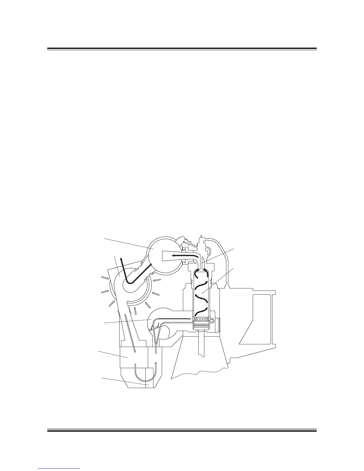
Exhaust Gas System
The exhaust gas is led from the cylinders to the
exhaust gas receiver where the uctuating pres-
sures from the cylinders are equalised and from
where the gas is led further on to the turbocharger
at a constant pressure. See g. 5.0.0.
Compensators are tted between the exhaust
valve housings and the exhaust gas receiver and
between the receiver and the turbocharger. A pro-
tective grating is placed between the exhaust gas
receiver and the turbocharger. The turbocharger
is tted with a pickup for monitoring and remote
indication of the turbocharger speed.
The exhaust gas receiver and the exhaust pipes
are provided with insulation, covered by steel
plating.
Turbocharger arrangement and cleaning systems
The turbochargers are located on the exhaust
side of the engine.
The engine is designed for the installation of the
MAN Diesel turbocharger types TCA (4 59 0),
ABB turbocharger type TPL (4 59 02), or MHI tur-
bocharger type MET (4 59 03).
All makes of turbochargers are tted with an ar-
rangement for water washing of the compressor
side, and soft blast cleaning of the turbine side,
see Figs. 5.02.02, 5.02.03 and 5.02.04. Wash-
ing of the turbine side is only applicable on MAN
Diesel and ABB turbochargers.
178 07 274.1
Fig. 15.01.01: Exhaust gas system on engine

 Loading...


