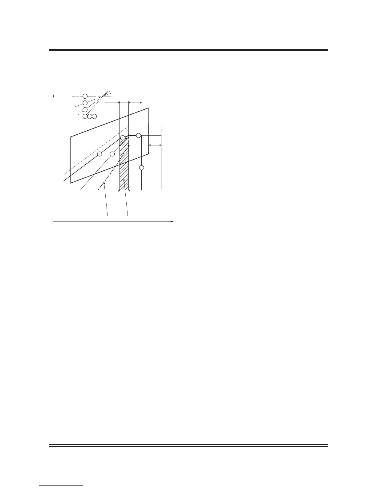
M Specied MCR of engine
O Matching point of engine
A Reference point of load diagram
S Continous service rating of engine
178 55 86-2.0
Example 5: Engine with Controllable Pitch Propeller
(CPP), with or without shaft generator
Layout diagram without shaft generator
If a controllable pitch propeller (CPP) is applied,
the combinator curve (of the propeller) will nor-
mally be selected for loaded ship including sea
margin.
The combinator curve may for a given propeller
speed have a given propeller pitch, and this may
be heavy running in heavy weather like for a xed
pitch propeller.
Therefore it is recommended to use a light run-
ning combinator curve (the dotted curve) as
shown in the gure to obtain an increased opera-
tion margin of the diesel engine in heavy weather
to the limit indicated by curves 4 and 5.
Layout diagram with shaft generator
The hatched area shows the recommended speed
range between 00% and 96.7% of the specied
MCR speed for an engine with shaft generator
running at constant speed.
The service point S can be located at any point
within the hatched area.
The procedure shown in examples 3 and 4 for
engines with FPP can also be applied here for en-
gines with CPP running with a combinator curve.
The matching point
O may be chosen on the propeller curve through
point A = M with a matching point from 85 to
00% of the specied MCR as mentioned before
in the section dealing with matching point O.
Load diagram
Therefore, when the engine’s specied MCR point
(M) has been chosen including engine margin,
sea margin and the power for a shaft generator, if
installed, point M may be used as point A of the
load diagram, which can then be drawn.
The position of the combinator curve ensures the
maximum load range within the permitted speed
range for engine operation, and it still leaves a
reasonable margin to the limit indicated by curves
4 and 5.
Example 6 will give a more detailed description of
how to run constant speed with a CP propeller.

 Loading...


