MAN B&W 2.04
Page of
MAN Diesel
MAN B&W ME/ME-C/ME-GI engines
198 38 97-3.6
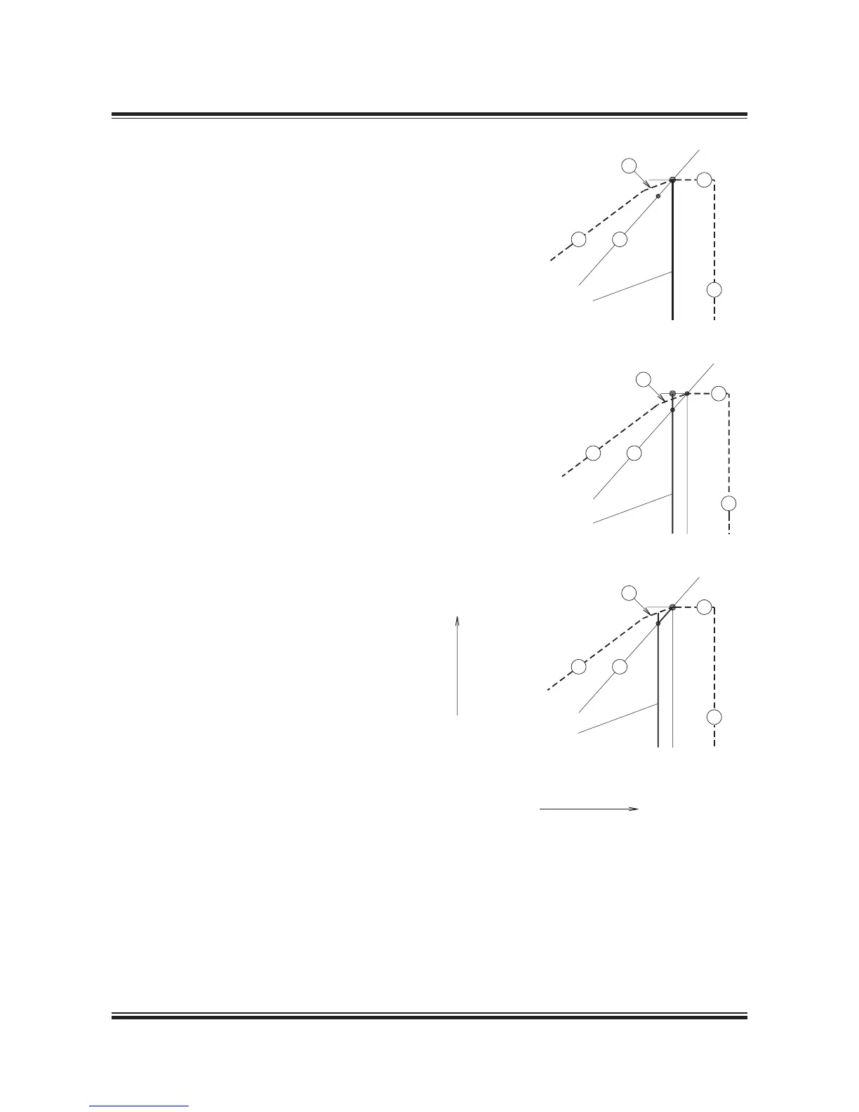
Example 6:
Engines running at constant speed with con-
trollable pitch propeller (CPP)
Fig. A Constant speed curve through M, normal
and correct location of the matching point O
Irrespective of whether the engine is operating on
a propeller curve or on a constant speed curve
through M, the matching point O must be located
on the propeller curve through the specied MCR
point M or, in special cases, to the left of point M.
The reason is that the propeller curve through
the matching point O is the layout curve of the
engine, and the intersection between curve and
the maximum power line 7 through point M is
equal to 00% power and 00% speed, point A of
the load diagram in this case A=M.
In Fig. A the matching point O has been placed
correctly, and the stepup gear and the shaft gen-
erator, if installed, may be synchronised on the
constant speed curve through M.
Fig. B: Constant speed curve through M, wrong
position of matching point O
If the engine has been servicematched at point O
on a constant speed curve through point M, then
the specied MCR point M would be placed out-
side the load diagram, and this is not permissible.
Fig. C: Recommended constant speed running
curve, lower than speed M
In this case it is assumed that a shaft generator,
if installed, is synchronised at a lower constant
main engine speed (for example with speed equal
to O or lower) at which improved CP propeller ef-
ciency is obtained for part load running.
In this layout example where an improved CP pro-
peller efciency is obtained during extended peri-
ods of part load running, the stepup gear and the
shaft generator have to be designed for the lower
constant engine speed that is applied.

 Loading...


