MAN B&W 7.01
Page of 3
MAN Diesel
MAN B&W ME/ME-B/MEC/MEGI engines 198 42 282.6
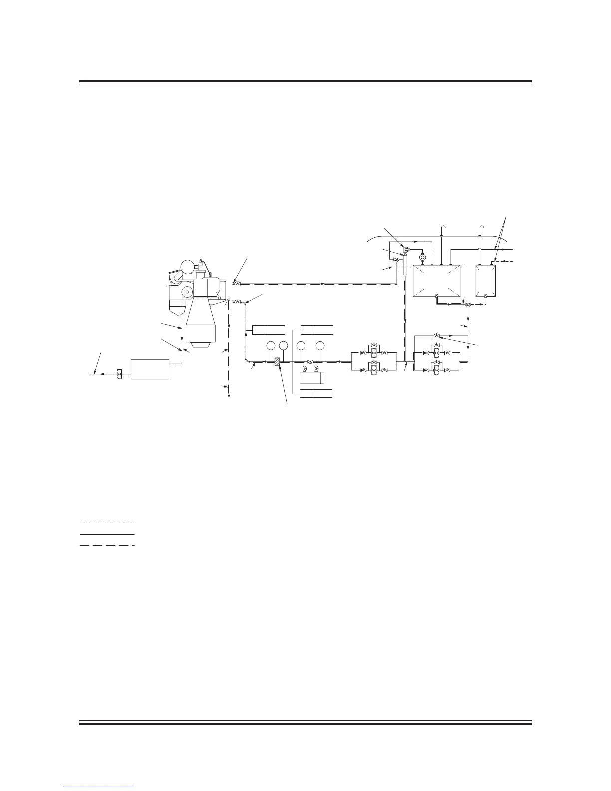
Fuel Oil System
Fig. 7.01.01: Fuel oil system
178 52 197.4
Diesel oil
Heavy fuel oil
Heated pipe with insulation
a) Tracing fuel oil lines: Max.50°C
b) Tracing drain lines: By jacket cooling water
The letters refer to the list of ‘Counteranges’
Deck
PI TI
Heater
PI TI
From centrifuges
Circulating pumps Supply pumps
D* )
d* )
D* )
32 mm Nominal bore
Aut. deaerating valve
Top of fuel oil service tank
Venting tank
Arr. of main engine fuel oil system.
(See Fig. 7.03.01)
F
X
AF
#
)
a)
a)
BD
To HFO settling tank
AD
b)
To jacket water
cooling pump
To sludge tank
No valve in drain pipe
between engine and tank
Fuel oil
drain tank
overflow tank
If the fuel oil pipe to engine is made as a straight line
immediately before the engine, it will be necessary to
mount an expansion unit. If the connection is made
as indicated, with a bend immediately before the
engine, no expansion unit is required.
Full flow filter.
For filter type see engine spec.
Overflow valve
Adjusted to 4 ba
Heavy fuel oil
service tank
Diesel
oil
service
tank
TE 8005
#) Approximately the following quantity of fuel oil should be treated in
the centrifuges: 0.23 l/kwh as explained in Section 7.05. The capacity of
the centrifuges to be according to manufacturer’s recommendation.
* ) D to have min. 50% larger passage area than d.
PT 8002
VT 8004

 Loading...


