MAN B&W 4.03
Page 3 of 6
MAN Diesel
198 43 156.2MAN B&W K108ME-C6, K98MC/MC-C/ME/ME-C6/7,
S90MC-C/ME-C7/8, K90ME/ME-C9, K90MC-C/ME-C6, S80MC6,
S80MC-C7/8, S80ME-C7/8/9, K80ME-C9, K80MC-C/ME-C6,
S70MCC/ME-C/ME-GI7/8, S70MC6, L70MCC/ME-C7/8,
S65ME-C/ME-GI8, S60MC6, S60MC-C/ME-C/ME-GI7/8,
L60MC-C/ME-C7/8, S50MC-C7/8, S50MC6, S50ME-B8/9
Crankshaft gear lubricated from the main engine lubricating oil system
The gures are to be added to the main engine capacity list:
Nominal output of generator kW 700 ,00 ,800 ,600
Lubricating oil ow m
3
/h 4. 4. 4.9 6.
Heat dissipation kW . 0.8 3. 45.0
RCF gear with separate lubricating oil system:
Nominal output of generator kW 700 ,00 ,800 ,600
Cooling water quantity m
3
/h 4. . 30.0 39.0
Heat dissipation kW 55 9 34 80
El. power for oil pump kW .0 5.0 8.0 .0
Dosage tank capacity m
3
0.40 0.5 0.69 0.95
El. power for Renkcontroller 4V DC ± 0%, 8 amp
From main engine:
Design lube oil pressure: .5 bar
Lube oil pressure at crankshaft gear: min. bar
Lube oil working temperature: 50 °C
Lube oil type: SAE 30
Fig. 4.03.02: Necessary capacities for PTO/RCF, BW III/RCF system
178 33 850.0
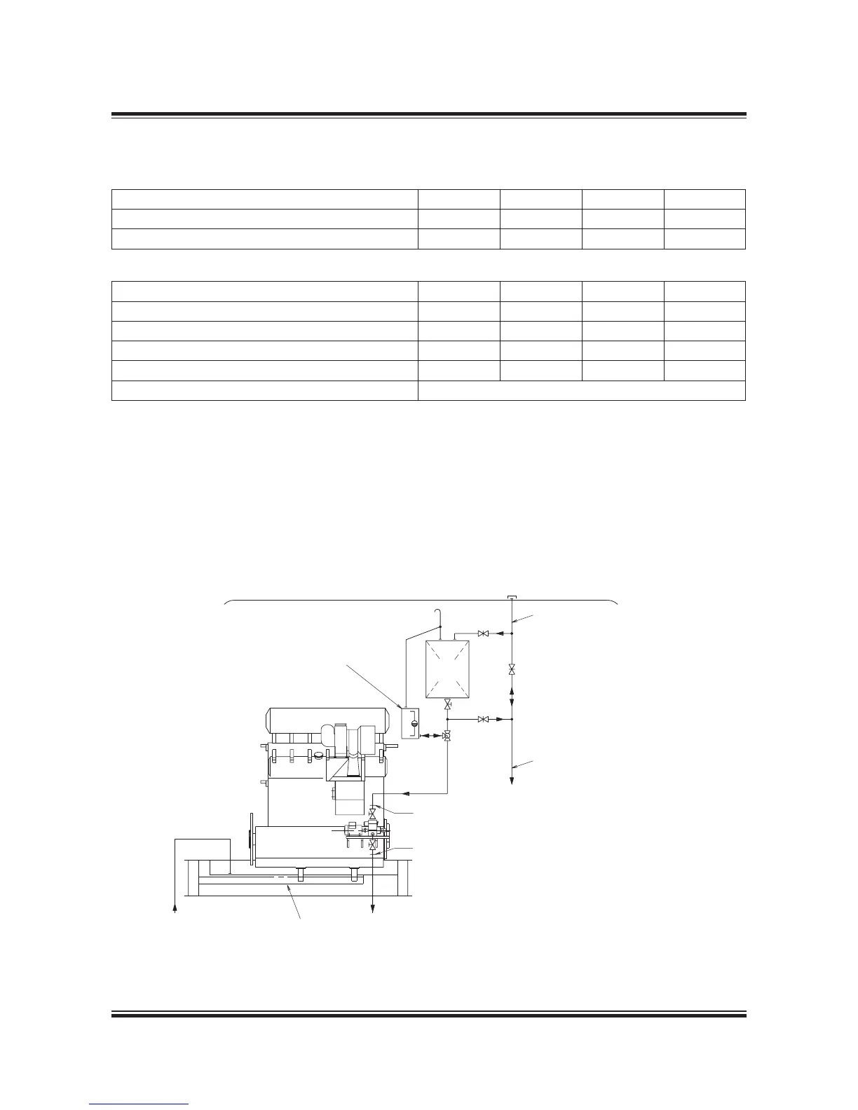
Cooling water inlet temperature: 36 °C
Pressure drop across cooler: approximately 0.5 bar
Fill pipe for lube oil system store tank (~ø3)
Drain pipe to lube oil system drain tank (~ø40)
Electric cable between Renk terminal at gearbox
and operator control panel in switchboard: Cable
type FMGCG 9 x x 0.5
The letters refer to the ‘List of anges’,
which will be extended by the engine builder,
when PTO systems are built on the main engine
Fig. 4.03.03: Lubricating oil system for RCF gear
178 25 235.0

 Loading...


