MAN B&W 4.01
Page of 6
MAN Diesel
198 43 000.2MAN B&W K108ME-C6, K98MC/MC-C/ME/ME-C6/7,
S90MC-C/ME-C7/8, K90ME/ME-C9, K90MC-C/ME-C6, S80MC6,
S80MC-C7/8, S80ME-C7/8/9, K80ME-C9, K80MC-C/ME-C6,
S70MCC/ME-C/ME-GI7/8, L70MCC/ME-C7/8, S70MC6,
S65ME-C/ME-GI8, S60MC6, S60MC-C/ME-C/ME-GI7/8,
L60MC-C/ME-C7/8, S50MC-C/ME-C7/8, S50MC6, S50ME-B8/9
PTO/RCF
Side mounted generator, BWIII/RCF
(Fig. .01.01, Alternative 3)
The PTO/RCF generator systems have been de-
veloped in close cooperation with the German
gear manufacturer RENK. A complete package
solution is offered, comprising a exible coupling,
a stepup gear, an epicyclic, variableratio gear
with builtin clutch, hydraulic pump and motor,
and a standard generator, see Fig. .01.03.
For marine engines with controllable pitch pro-
pellers running at constant engine speed, the
hydraulic system can be dispensed with, i.e. a
PTO/GCR design is normally used.
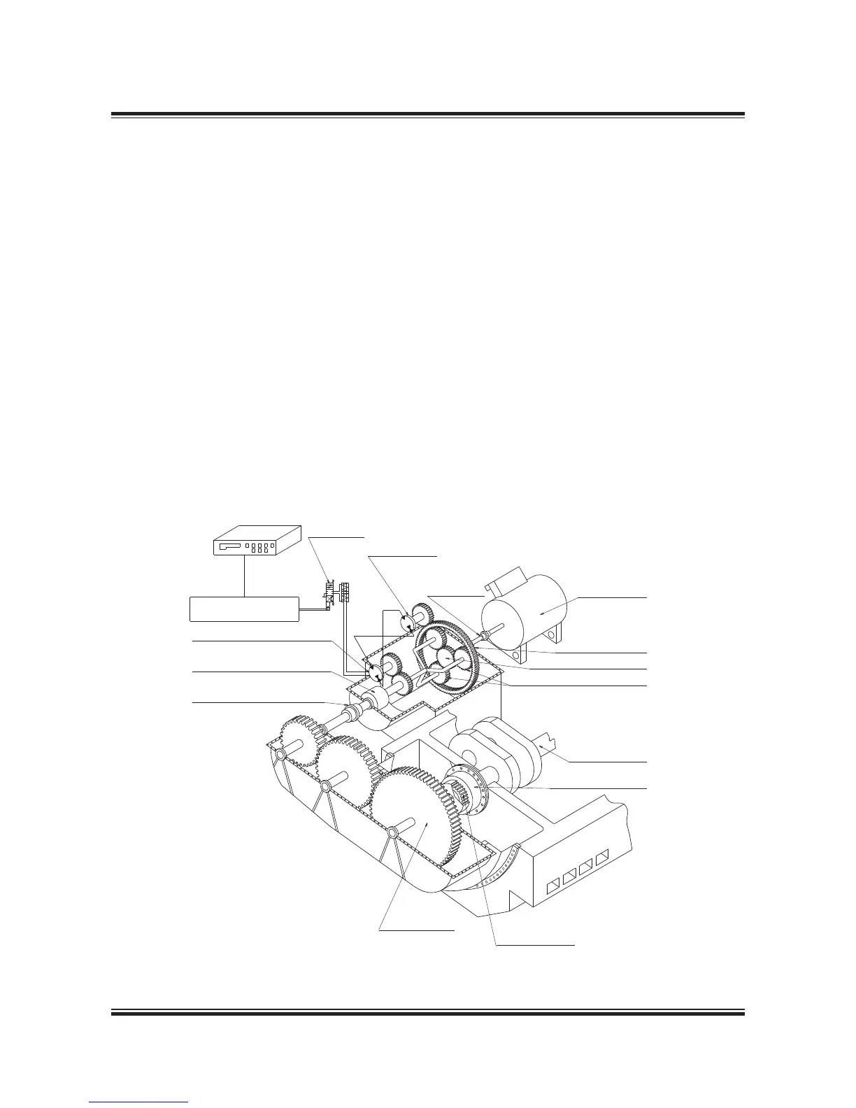
Fig. .01.03 shows the principles of the PTO/RCF
arrangement. As can be seen, a stepup gear box
(called crankshaft gear) with three gear wheels
is bolted directly to the frame box of the main
engine. The bearings of the three gear wheels
are mounted in the gear box so that the weight of
the wheels is not carried by the crankshaft. In the
frame box, between the crankcase and the gear
drive, space is available for tuning wheel, counter-
weights, axial vibration damper, etc.
The rst gear wheel is connected to the crank-
shaft via a special exible coupling made in one
piece with a tooth coupling driving the crankshaft
gear, thus isolating it against torsional and axial
vibrations.
By means of a simple arrangement, the shaft in
the crankshaft gear carrying the rst gear wheel
and the female part of the toothed coupling can
be moved forward, thus disconnecting the two
parts of the toothed coupling.

 Loading...


